Projection points whose coincidence are called. Drawing lesson "constructing projections of points on the surface of an object"
Goals:
- Studying the rules for constructing projections of points on the surface of an object and reading drawings.
- Develop spatial thinking, the ability to analyze the geometric shape of an object.
- To cultivate diligence, the ability to cooperate when working in groups, and interest in the subject.
DURING THE CLASSES
STAGE I. MOTIVATION OF LEARNING ACTIVITIES.
STAGE II. FORMATION OF KNOWLEDGE, ABILITIES AND SKILLS.
HEALTH-SAVING PAUSE. REFLECTION (MOOD)
STAGE III. INDIVIDUAL WORK.
STAGE I. MOTIVATION OF LEARNING ACTIVITIES
1) Teacher: Check your workplace, is everything in place? Is everyone ready to go?
TAKE A DEEP BREATH, HOLD YOUR BREATH AS YOU EXHALE, BREATH OUT.
Determine your mood at the beginning of the lesson according to the diagram (this diagram is on everyone’s desk)
I WISH YOU GOOD LUCK.
2)Teacher: Practical work on the topic “ Projections of vertices, edges, faces” showed that there are guys who make mistakes when projecting. They are confused which of two coinciding points in the drawing is a visible vertex and which is an invisible one; when the edge is parallel to the plane, and when it is perpendicular. It's the same with edges.
To prevent the repetition of mistakes, complete the necessary tasks using the counseling card and correct errors in practical work (by hand). And as you work, remember:
“EVERYONE CAN MAKE A MISTAKE, ONLY A CRAZY ONE STAYS WITH THEIR ERROR.”
And those who have mastered the topic well will work in groups with creative tasks (see. Annex 1 ).
STAGE II. FORMATION OF KNOWLEDGE, ABILITIES AND SKILLS
1)Teacher: In production there are many parts that are attached to each other in a certain way.
For example:
The desktop cover is attached to the vertical posts. Pay attention to the table you are at, how and with what are the lid and racks attached to each other?
Answer: Bolt.
Teacher: What is needed for a bolt?
Answer: Hole.
Teacher: Really. And in order to make a hole, you need to know its location on the product. When making a table, a carpenter cannot contact the customer every time. So, what do you need to provide a carpenter with?
Answer: A drawing.
Teacher: Drawing!? What do we call a drawing?
Answer: A drawing is an image of an object using rectangular projections in a projection relationship. Using the drawing, you can imagine the geometric shape and design of the product.
Teacher: We have completed rectangular projections, what next? Will we be able to determine the location of the holes from one projection? What else do we need to know? What to learn?
Answer: Construct points. Find the projections of these points in all views.
Teacher: Well done! This is the goal of our lesson and topic: Construction of projections of points on the surface of an object. Write the topic of the lesson in your notebook.
You and I know that any point or segment on the image of an object is a projection of a vertex, edge, face, i.e. each view is an image not from one side (head view, top view, left view), but the entire object.
In order to correctly find the projections of individual points lying on the faces, you must first find the projections of this face, and then, using connection lines, find the projections of the points.
(We look at the drawing on the board, work in a notebook, where 3 projections of the same part are made at home).

– Opened the notebook with the completed drawing (Explanation of the construction of points on the surface of an object with guiding questions on the board, and students fix it in their notebooks.)
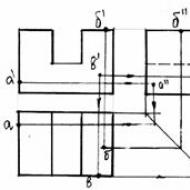
Teacher: Consider the point IN. Which plane is the face of this point parallel to?
Answer: The edge is parallel to the frontal plane.
Teacher: We define the projection of a point b' on the frontal projection. Swipe down from the point b' vertical communication line to the horizontal projection. Where will the horizontal projection of the point be located? IN?
Answer: At the intersection with the horizontal projection of the face that was projected into the edge. And it is located at the bottom of the projection (view).
Teacher: Profile projection of a point b'' , where will it be located? How will we find her?
Answer: At the intersection of a horizontal communication line from b' with a vertical edge on the right. This edge is the projection of the face with the point IN.
THOSE WHO WANT TO CONSTRUCT THE NEXT PROJECTION OF THE POINT ARE CALLED TO THE BOARD.
Teacher: Point projections A are also located using communication lines. Which plane is the face with the point parallel to? A?
Answer: The edge is parallel to the profile plane. We define a point on the profile projection A'' .
Teacher: In which projection was the face projected into the edge?
Answer: On the front and horizontal. Let's draw a horizontal connection line until it intersects with the vertical edge on the left on the frontal projection, we get a point A' .
Teacher: How to find the projection of a point A on a horizontal projection? After all, communication lines from the projection of points A' And A'' do not intersect the projection of the face (edge) on the horizontal projection on the left. What can help us?
Answer: You can use a constant straight line (it determines the location of the view on the left) from A'' draw a vertical communication line until it intersects with a constant straight line. A horizontal connection line is drawn from the intersection point until it intersects with the vertical edge on the left. (This is the face with point A) and denotes the projection with a point A .
2) Teacher: Everyone has a task card on the table with tracing paper attached. Examine the drawing, now try on your own, without redrawing the projections, to find the given projections of points in the drawing.

– Find the picture in the textbook, page 76. 93. Test yourself. Those who did it correctly – score “5”; one mistake – ‘’4’’; two – ‘’3’’.
(Grades are given by the students themselves on the self-control sheet).
– Collect cards for verification.
3)Work in groups: Time limited: 4 min. + 2 min. checks. (Two desks with students are combined, and a leader is selected within the group).
Each group is given tasks in 3 levels. Students choose tasks by level (as they wish). Solve problems involving constructing points. Discuss the formation under the supervision of the leader. Then the correct answer is displayed on the board using an overhead projector. Everyone checks that the projection of the points is done correctly. With the help of the group leader, grades are given on assignments and on self-control sheets (see. Appendix 2 And Appendix 3 ).
HEALTH-SAVING PAUSE. REFLECTION
“Pharaoh Pose”– sit on the edge of a chair, straighten your back, bend your arms at the elbows, cross your legs and place them on your toes. Inhale, tense all the muscles of the body while holding your breath, exhale. Do it 2-3 times. Close your eyes tightly, until they reach the stars, and open them. Mark your mood.
STAGE III. PRACTICAL PART. (Individual assignments)
There are task cards available to choose from at different levels. Students choose their own option according to their abilities. Find the projections of points on the surface of the object. Works are submitted and graded for the next lesson. (Cm. Appendix 4 , Appendix 5 , Appendix 6 ).
IV STAGE. FINAL
1) Homework assignment. (Instruction). Performed by levels:
B – understanding, at “3”. Exercise 1 Fig. 94a p. 77 – according to the assignment in the textbook: complete the missing projections of points on these projections.
B – application, at “4”. Exercise 1 Fig. 94 a, b. complete the missing projections and mark the vertices on the visual image in 94a and 94b.
A – analysis, “5”. (Increased difficulty.) Ex. 4 Fig.97 – construct the missing projections of the points and label them with letters. There is no visual image.
2)Reflexive analysis.
- Determine the mood at the end of the lesson, mark it with any sign on the self-control sheet.
- What new did you learn in class today?
- What form of work is most effective for you: group, individual, and would you like it to be repeated in the next lesson?
- Collect self-control sheets.
3)“The Mistaken Teacher”
Teacher: You have learned to construct projections of vertices, edges, faces and points on the surface of an object, following all the rules of construction. But they gave you a drawing that contains errors. Now try yourself as a teacher. Find the errors yourself, if you find all 8–6 errors, then the score is “5”; 5–4 errors – “4”, 3 errors – “3”.

Answers:

Projection apparatus
The projection apparatus (Fig. 1) includes three projection planes:
π 1 – horizontal projection plane;
π 2 – frontal plane of projections;
π 3– profile projection plane .
The projection planes are mutually perpendicular ( π 1^ π 2^ π 3), and their intersection lines form the axes:
Intersection of planes π 1 And π 2 form an axis 0X (π 1∩ π 2 = 0X);
Intersection of planes π 1 And π 3 form an axis 0Y (π 1∩ π 3 = 0Y);
Intersection of planes π 2 And π 3 form an axis 0Z (π 2∩ π 3 = 0Z).
The intersection point of the axes (OX∩OY∩OZ=0) is considered the starting point (point 0).
Since the planes and axes are mutually perpendicular, such an apparatus is similar to the Cartesian coordinate system.
The projection planes divide the entire space into eight octants (in Fig. 1 they are indicated by Roman numerals). Projection planes are considered opaque, and the viewer is always in I-th octant.
Orthogonal projection with projection centers S 1, S 2 And S 3 respectively for horizontal, frontal and profile projection planes.
A.
From projection centers S 1, S 2 And S 3 projecting rays come out l 1, l 2 And l 3 A
- A 1 A;
- A 2– frontal projection of a point A;
- A 3– profile projection of a point A.
A point in space is characterized by its coordinates A(x,y,z). Points A x, A y And A z respectively on the axes 0X, 0Y And 0Z show coordinates x, y And z points A. In Fig. 1 gives all the necessary notations and shows the connections between the point A space, its projections and coordinates.
Point diagram
To get a plot of a point A(Fig. 2), in the projection apparatus (Fig. 1) the plane π 1 A 1 0X π 2. Then the plane π 3 with point projection A 3, rotate counterclockwise around the axis 0Z, until it is aligned with the plane π 2. Direction of plane rotations π 2 And π 3 shown in Fig. 1 arrows. At the same time, straight A 1 A x And A 2 A x 0X perpendicular A 1 A 2, and the straight lines A 2 A x And A 3 A x will be located on a common axis 0Z perpendicular A 2 A 3. In what follows we will call these lines respectively vertical And horizontal communication lines.
It should be noted that when moving from the projection apparatus to the diagram, the projected object disappears, but all information about its shape, geometric dimensions and its location in space is preserved.
A(x A , y A , z Ax A , y A And zA in the following sequence (Fig. 2). This sequence is called the method of constructing a point diagram.
1. Axes are drawn orthogonally OX, OY And OZ.
2. On the axis OX x A points A and get the position of the point A x.
3. Through the point A x perpendicular to the axis OX
A x along the axis OY the numerical value of the coordinate is plotted y A points A A 1 on the diagram.
A x along the axis OZ the numerical value of the coordinate is plotted zA points A A 2 on the diagram.

6. Through the point A 2 parallel to the axis OX a horizontal communication line is drawn. The intersection of this line and the axis OZ will give the position of the point A z.
7. On a horizontal communication line from a point A z along the axis OY the numerical value of the coordinate is plotted y A points A and the position of the profile projection of the point is determined A 3 on the diagram.
Characteristics of points
All points in space are divided into points of particular and general positions.
Points of particular position. The points belonging to the projection apparatus are called points of particular position. These include points belonging to projection planes, axes, origins and projection centers. The characteristic features of particular position points are:
Metamathematical – one, two or all numerical coordinate values are equal to zero and (or) infinity;
On a diagram, two or all projections of a point are located on the axes and (or) located at infinity.
Points of general position. Points of general position include points that do not belong to the projection apparatus. For example, dot A in Fig. 1 and 2.
In the general case, the numerical values of the coordinates of a point characterize its distance from the projection plane: coordinate X from the plane π 3; coordinate y from the plane π 2; coordinate z from the plane π 1. It should be noted that the signs for the numerical values of the coordinates indicate the direction in which the point moves away from the projection planes. Depending on the combination of signs for the numerical values of the coordinates of a point, it depends on which octane it is in.
Two Image Method
In practice, in addition to the full projection method, the two-image method is used. It differs in that this method eliminates the third projection of the object. To obtain the projection apparatus of the two-image method, the profile projection plane with its projection center is excluded from the full projection apparatus (Fig. 3). Moreover, on the axis 0X a reference point is assigned (point 0 ) and from it perpendicular to the axis 0X in projection planes π 1 And π 2 draw axes 0Y And 0Z respectively.

In this device, the entire space is divided into four quadrants. In Fig. 3 they are indicated by Roman numerals.
Projection planes are considered opaque, and the viewer is always in I-th quadrant.
Let's consider the operation of the device using the example of projecting a point A.
From projection centers S 1 And S 2 projecting rays come out l 1 And l 2. These rays pass through the point A and intersecting with the projection planes form its projections:
- A 1– horizontal projection of a point A;
- A 2– frontal projection of a point A.
To get a plot of a point A(Fig. 4), in the projection apparatus (Fig. 3) the plane π 1 with the resulting projection of the point A 1 rotate clockwise around an axis 0X, until it is aligned with the plane π 2. Direction of plane rotation π 1 shown in Fig. 3 arrows. In this case, on the diagram of a point obtained by the method of two images, only one remains vertical communication line A 1 A 2.

In practice, plotting a point A(x A , y A , z A) is carried out according to the numerical values of its coordinates x A , y A And zA in the following sequence (Fig. 4).
1. The axis is drawn OX and a reference point is assigned (point 0 ).
2. On the axis OX the numerical value of the coordinate is plotted x A points A and get the position of the point A x.
3. Through the point A x perpendicular to the axis OX a vertical communication line is drawn.
4. On a vertical communication line from a point A x along the axis OY the numerical value of the coordinate is plotted y A points A and the position of the horizontal projection of the point is determined A 1 OY is not drawn, but it is assumed that its positive values are located below the axis OX, and negative ones are higher.
5. On a vertical communication line from a point A x along the axis OZ the numerical value of the coordinate is plotted zA points A and the position of the frontal projection of the point is determined A 2 on the diagram. It should be noted that in the diagram the axis OZ is not drawn, but it is assumed that its positive values are located above the axis OX, and negative ones are lower.
Competing points
Points on the same projecting beam are called competing points. In the direction of the projecting beam, they have a common projection for them, i.e. their projections are identical. A characteristic feature of competing points on the diagram is the identical coincidence of their projections of the same name. The competition lies in the visibility of these projections relative to the observer. In other words, in space for an observer one of the points is visible, the other is not. And, accordingly, in the drawing: one of the projections of the competing points is visible, and the projection of the other point is invisible.
On the spatial projection model (Fig. 5) from two competing points A And IN visible point A according to two mutually complementary characteristics. Judging by the chain S 1 →A→B dot A closer to the observer than the point IN. And, accordingly, further from the projection plane π 1(those. zA > zA).

Rice. 5 Fig.6
If the point itself is visible A, then its projection is also visible A 1. In relation to the projection coinciding with it B 1. For clarity and, if necessary, on the diagram, invisible projections of points are usually enclosed in brackets.
Let's remove the points on the model A And IN. Their coinciding projections on the plane will remain π 1 and separate projections – on π 2. Let us conditionally leave the frontal projection of the observer (⇩) located in the center of projection S 1. Then, along the chain of images ⇩ → A 2 → B 2 it will be possible to judge that zA > z B and that the point itself is visible A and its projection A 1.
Let us similarly consider competing points WITH And D in appearance relative to the π 2 plane. Since the common projecting beam of these points l 2 parallel to the axis 0Y, then a sign of the visibility of competing points WITH And D determined by inequality y C > y D. Therefore, that point D closed by a dot WITH and accordingly the projection of the point D 2 will be covered by the projection of the point C 2 on surface π 2.
Let's consider how the visibility of competing points in a complex drawing is determined (Fig. 6).
Judging by the coincident projections A 1≡IN 1 the points themselves A And IN are on one projecting beam parallel to the axis 0Z. This means that the coordinates can be compared zA And z B these points. To do this, we use the frontal projection plane with separate images of the points. In this case zA > z B. It follows from this that the projection is visible A 1.
Points C And D in the complex drawing under consideration (Fig. 6) are also on the same projecting beam, but only parallel to the axis 0Y. Therefore, from comparison y C > y D we conclude that projection C 2 is visible.
General rule. Visibility for matching projections of competing points is determined by comparing the coordinates of those points in the direction of a common projection ray. The projection of the point whose coordinate is greater is visible. In this case, the coordinates are compared on the projection plane with separate images of the points.
The position of a point in space can be specified by its two orthogonal projections, for example, horizontal and frontal, frontal and profile. The combination of any two orthogonal projections allows you to find out the value of all the coordinates of a point, construct a third projection, and determine the octant in which it is located. Let's look at several typical problems from the descriptive geometry course.
For a given complex drawing of points A and B, it is necessary:
Let us first determine the coordinates of point A, which can be written in the form A (x, y, z). Horizontal projection of point A - point A", having coordinates x, y. Let us draw perpendiculars from point A" to the x, y axes and find A x, A y, respectively. The x coordinate for point A is equal to the length of the segment A x O with a plus sign, since A x lies in the region of positive values of the x axis. Taking into account the scale of the drawing, we find x = 10. The y coordinate is equal to the length of the segment A y O with a minus sign, since t. A y lies in the region of negative values of the y axis. Taking into account the scale of the drawing, y = –30. The frontal projection of point A - point A"" has coordinates x and z. Let's drop the perpendicular from A"" to the z axis and find A z. The z coordinate of point A is equal to the length of the segment A z O with a minus sign, since A z lies in the region of negative values of the z axis. Taking into account the drawing scale z = –10. Thus, the coordinates of point A are (10, –30, –10).
The coordinates of point B can be written as B (x, y, z). Consider the horizontal projection of point B - point B". Since it lies on the x axis, then B x = B" and the coordinate B y = 0. The abscissa x of point B is equal to the length of the segment B x O with a plus sign. Taking into account the drawing scale x = 30. The frontal projection of point B is t. B˝ has coordinates x, z. Let's draw a perpendicular from B"" to the z axis, thus finding B z. The applicate z of point B is equal to the length of the segment B z O with a minus sign, since B z lies in the region of negative values of the z axis. Taking into account the scale of the drawing, we determine the value z = –20. So the coordinates of B are (30, 0, -20). All necessary constructions are presented in the figure below.

Construction of projections of points
Points A and B in plane P 3 have the following coordinates: A""" (y, z); B""" (y, z). In this case, A"" and A""" lie on the same perpendicular to the z axis, since they have a common z coordinate. Similarly, B"" and B""" lie on a common perpendicular to the z axis. To find the profile projection of point A, we plot along the y-axis the value of the corresponding coordinate found earlier. In the figure, this is done using a circular arc of radius A y O. After this, draw a perpendicular from A y until it intersects with the perpendicular restored from point A"" to the z axis. The intersection point of these two perpendiculars determines the position of A""".
Point B""" lies on the z axis, since the y ordinate of this point is zero. To find the profile projection of point B in this problem, you only need to draw a perpendicular from B"" to the z axis. The intersection point of this perpendicular with the z axis is B """.

Determining the position of points in space
Visually imagining the spatial layout, composed of projection planes P 1, P 2 and P 3, the location of the octants, as well as the order of transforming the layout into diagrams, you can directly determine that point A is located in the III octant, and point B lies in the plane P 2.
Another option for solving this problem is the method of exceptions. For example, the coordinates of point A are (10, -30, -10). A positive abscissa x allows us to judge that the point is located in the first four octants. A negative y-ordinate indicates that the point is in the second or third octant. Finally, the negative applicate z indicates that point A is located in the third octant. The following table clearly illustrates the above reasoning.
| Octants | Coordinate signs | ||
| x | y | z | |
| 1 | + | + | + |
| 2 | + | – | + |
| 3 | + | – | – |
| 4 | + | + | – |
| 5 | – | + | + |
| 6 | – | – | + |
| 7 | – | – | – |
| 8 | – | + | – |
Coordinates of point B (30, 0, -20). Since the ordinate of point B is zero, this point is located in the projection plane P 2. The positive abscissa and negative applicate of t. B indicate that it is located on the border of the third and fourth octants.
Construction of a visual image of points in the system of planes P 1, P 2, P 3

Using a frontal isometric projection, we built a spatial layout of the III octant. It is a rectangular trihedron, whose faces are the planes P 1, P 2, P 3, and the angle (-y0x) is 45 º. In this system, segments along the x, y, z axes will be plotted in natural size without distortion.
Let's start constructing a visual image of point A (10, -30, -10) with its horizontal projection A. Having plotted the corresponding coordinates along the abscissa and ordinate axis, we find the points A x and A y. The intersection of perpendiculars reconstructed from A x and A y respectively to the x and y axes determines the position of point A". Laying off from A" parallel to the z axis towards its negative values the segment AA", the length of which is 10, we find the position of point A.
The visual image of point B (30, 0, -20) is constructed in a similar way - in the P2 plane along the x and z axes, you need to plot the corresponding coordinates. The intersection of the perpendiculars reconstructed from B x and B z will determine the position of point B.
Let's consider the projections of points onto two planes, for which we take two perpendicular planes (Fig. 4), which we will call horizontal frontal and planes. The line of intersection of these planes is called the projection axis. We project one point A onto the considered planes using a plane projection. To do this, it is necessary to lower the perpendiculars Aa and A from a given point onto the considered planes.
The projection onto the horizontal plane is called horizontal projection points A, and the projection A? on the frontal plane is called frontal projection.
Points to be projected are usually denoted in descriptive geometry using capital letters A, B, C. Small letters are used to indicate horizontal projections of points a, b, c... Frontal projections are indicated in small letters with a stroke at the top a?, b?, c?…
Points are also designated by Roman numerals I, II,... and for their projections - by Arabic numerals 1, 2... and 1?, 2?...
By rotating the horizontal plane by 90°, you can get a drawing in which both planes are in the same plane (Fig. 5). This picture is called diagram of a point.

Through perpendicular lines Ahh And Huh? Let's draw a plane (Fig. 4). The resulting plane is perpendicular to the frontal and horizontal planes because it contains perpendiculars to these planes. Therefore, this plane is perpendicular to the line of intersection of the planes. The resulting straight line intersects the horizontal plane in a straight line ahh x, and the frontal plane – in a straight line a?a X. Straight aahs and a?a x are perpendicular to the axis of intersection of the planes. That is Aahaha? is a rectangle.
When combining horizontal and frontal projection planes A And A? will lie on the same perpendicular to the axis of intersection of the planes, since when the horizontal plane rotates, the perpendicularity of the segments ahh x and a?a x will not be broken.
We get that on the projection diagram A And A? some point A always lie on the same perpendicular to the axis of intersection of the planes.
Two projections a and A? of a certain point A can unambiguously determine its position in space (Fig. 4). This is confirmed by the fact that when constructing a perpendicular from projection a to the horizontal plane, it will pass through point A. In the same way, a perpendicular from projection A? to the frontal plane will pass through the point A, i.e. point A is simultaneously on two specific straight lines. Point A is their point of intersection, that is, it is definite.
Consider a rectangle Aaa X A?(Fig. 5), for which the following statements are true:
1) Point distance A from the frontal plane is equal to the distance of its horizontal projection a from the axis of intersection of the planes, i.e.
Huh? = ahh X;
2) point distance A from the horizontal plane of projections is equal to the distance of its frontal projection A? from the axis of intersection of the planes, i.e.
Ahh = a?a X.
In other words, even without the point itself on the diagram, using only its two projections, you can find out at what distance a given point is located from each of the projection planes.
The intersection of two projection planes divides space into four parts, which are called in quarters(Fig. 6).
The axis of intersection of the planes divides the horizontal plane into two quarters - the front and rear, and the frontal plane - into the upper and lower quarters. The upper part of the frontal plane and the anterior part of the horizontal plane are considered as the boundaries of the first quarter.

When receiving the diagram, the horizontal plane rotates and is aligned with the frontal plane (Fig. 7). In this case, the front part of the horizontal plane will coincide with the bottom part of the frontal plane, and the back part of the horizontal plane will coincide with the top part of the frontal plane.

Figures 8-11 show points A, B, C, D, located in different quarters of space. Point A is located in the first quarter, point B is in the second, point C is in the third and point D is in the fourth.

When the points are located in the first or fourth quarters of them horizontal projections are on the front part of the horizontal plane, and on the diagram they will lie below the axis of intersection of the planes. When a point is located in the second or third quarter, its horizontal projection will lie on the back of the horizontal plane, and on the diagram it will be located above the axis of intersection of the planes.

Frontal projections points that are located in the first or second quarters will lie on the upper part of the frontal plane, and on the diagram they will be located above the axis of intersection of the planes. When a point is located in the third or fourth quarter, its frontal projection is below the axis of intersection of the planes.
Most often, in real constructions, the figure is placed in the first quarter of space.
In some special cases, the point ( E) can lie on a horizontal plane (Fig. 12). In this case, its horizontal projection e and the point itself will coincide. The frontal projection of such a point will be located on the axis of intersection of the planes.
In the case when the point TO lies on the frontal plane (Fig. 13), its horizontal projection k lies on the axis of intersection of the planes, and the frontal k? shows the actual location of this point.

For such points, a sign that it lies on one of the projection planes is that one of its projections is on the axis of intersection of the planes.
If a point lies on the axis of intersection of the projection planes, it and both of its projections coincide.
When a point does not lie on the projection planes, it is called point of general position. In what follows, if there are no special marks, the point in question is a point in general position.
2. Lack of projection axis
To explain how to obtain projections of a point on a model perpendicular to the projection plane (Fig. 4), it is necessary to take a piece of thick paper in the shape of an elongated rectangle. It needs to be bent between projections. The fold line will represent the axis of intersection of the planes. If after this the bent piece of paper is straightened again, we will get a diagram similar to the one shown in the figure.
By combining two projection planes with the drawing plane, it is possible not to show the fold line, i.e., not to draw the axis of intersection of the planes on the diagram.
When plotting on a diagram, you should always place projections A And A? point A on one vertical line (Fig. 14), which is perpendicular to the axis of intersection of the planes. Therefore, even if the position of the axis of intersection of the planes remains uncertain, but its direction is determined, the axis of intersection of the planes can only be located on the diagram perpendicular to the straight line huh?.

If there is no projection axis on the diagram of a point, as in the first Figure 14 a, you can imagine the position of this point in space. To do this, draw anywhere perpendicular to the straight line huh? projection axis, as in the second figure (Fig. 14) and bend the drawing along this axis. If we restore perpendiculars at points A And A? before they intersect, you can get a point A. When changing the position of the projection axis, different positions of the point relative to the projection planes are obtained, but the uncertainty of the position of the projection axis does not affect the relative position of several points or figures in space.
3. Projections of a point onto three projection planes
Let's consider the profile plane of projections. Projections onto two perpendicular planes usually determine the position of a figure and make it possible to find out its real size and shape. But there are times when two projections are not enough. Then the construction of the third projection is used.
The third projection plane is drawn so that it is perpendicular to both projection planes simultaneously (Fig. 15). The third plane is usually called profile.
In such constructions, the common straight line of the horizontal and frontal planes is called axis X , the common straight line of the horizontal and profile planes – axis at , and the common straight line of the frontal and profile planes is axis z . Dot ABOUT, which belongs to all three planes, is called the origin point.

Figure 15a shows the point A and three of its projections. Projection onto the profile plane ( A??) are called profile projection and denote A??.
To obtain a diagram of point A, which consists of three projections a, a, a, it is necessary to cut the trihedron formed by all the planes along the y-axis (Fig. 15b) and combine all these planes with the plane of the frontal projection. The horizontal plane must be rotated about the axis X, and the profile plane is about the axis z in the direction indicated by the arrow in Figure 15.
Figure 16 shows the position of the projections huh, huh? And A?? points A, obtained by combining all three planes with the drawing plane.
As a result of the cut, the y-axis appears in two different places on the diagram. On a horizontal plane (Fig. 16) it takes a vertical position (perpendicular to the axis X), and on the profile plane – horizontal (perpendicular to the axis z).

There are three projections in Figure 16 huh, huh? And A?? points A have a strictly defined position on the diagram and are subject to unambiguous conditions:
A And A? should always be located on the same vertical line, perpendicular to the axis X;
A? And A?? should always be located on the same horizontal straight line, perpendicular to the axis z;
3) when carried out through a horizontal projection and a horizontal straight line, and through a profile projection A??– a vertical straight line, the constructed straight lines will necessarily intersect on the bisector of the angle between the projection axes, since the figure Oa at A 0 A n – square.
When constructing three projections of a point, you need to check whether all three conditions are met for each point.
4. Point coordinates
The position of a point in space can be determined using three numbers called its coordinates. Each coordinate corresponds to the distance of a point from some projection plane.
Determined point distance A to the profile plane is the coordinate X, wherein X = huh?Huh(Fig. 15), the distance to the frontal plane is coordinate y, and y = huh?Huh, and the distance to the horizontal plane is the coordinate z, wherein z = aA.
In Figure 15, point A occupies the width of a rectangular parallelepiped, and the measurements of this parallelepiped correspond to the coordinates of this point, i.e., each of the coordinates is represented in Figure 15 four times, i.e.:
x = a?A = Oa x = a y a = a z a?;
y = а?А = Оа y = а x а = а z а?;
z = aA = Oa z = a x a? = a y a?.
In the diagram (Fig. 16), the x and z coordinates appear three times:
x = a z a?= Oa x = a y a,
z = a x a? = Oa z = a y a?.
All segments that correspond to the coordinate X(or z), are parallel to each other. Coordinate at represented twice by an axis located vertically:
y = Oa y = a x a
and twice – located horizontally:
y = Oa y = a z a?.
This difference appears due to the fact that the y-axis is present on the diagram in two different positions.
It should be taken into account that the position of each projection is determined on the diagram by only two coordinates, namely:
1) horizontal – coordinates X And at,
2) frontal – coordinates x And z,
3) profile – coordinates at And z.
Using coordinates x, y And z, you can construct projections of a point on a diagram.
If point A is given by coordinates, their recording is defined as follows: A ( X; y; z).
When constructing point projections A the following conditions must be checked:
1) horizontal and frontal projections A And A? X X;
2) frontal and profile projections A? And A? must be located at the same perpendicular to the axis z, since they have a common coordinate z;
3) horizontal projection and also removed from the axis X, like profile projection A away from the axis z, since projections ah? and eh? have a common coordinate at.
If a point lies in any of the projection planes, then one of its coordinates is equal to zero.
When a point lies on the projection axis, two of its coordinates are equal to zero.
If a point lies at the origin, all three of its coordinates are zero.
|
Verbal form |
Graphic form |
|
1. Plot the corresponding coordinates of point A on the X, Y, Z axes. We obtain points A x, A y, A z | |
|
2. Horizontal projection A 1 is located at the intersection of communication lines from points A x and A y drawn parallel to the X and Y axes |
|
|
3. Frontal projection A 2 is located at the intersection of communication lines from points A x and A z drawn parallel to the X and Z axes |
|
|
4. Profile projection A 3 is located at the intersection of communication lines from points A z and A y drawn parallel to the Z and Y axes |
|
3.2. Position of the point relative to the projection planes
The position of a point in space relative to the projection planes is determined by its coordinates. The X coordinate determines the distance of a point from the P 3 plane (projection onto P 2 or P 1), the Y coordinate determines the distance from the P 2 plane (projection onto P 3 or P 1), the Z coordinate determines the distance from the P 1 plane (projection onto P 3 or P 2). Depending on the value of these coordinates, a point can occupy both a general and a particular position in space in relation to the projection planes (Fig. 3.1).

Rice. 3.1. Point classification
Tpointsgeneralprovisions. The coordinates of a generic point are not equal to zero ( x≠0, y≠0, z≠0 ), and depending on the sign of the coordinate, the point can be located in one of eight octants (Table 2.1).
In Fig. 3.2 provides drawings of points in general position. Analysis of their images allows us to conclude that they are located in the following octants of space: A(+X;+Y; +Z( Ioctant;B(+X;+Y;-Z( IVoctant;C(-X;+Y; +Z( Voctant;D(+X;+Y; +Z( IIoctant.
Points of special position. One of the coordinates at a point of particular position is equal to zero, so the projection of the point lies on the corresponding projection field, the other two - on the projection axes. In Fig. 3.3 such points are points A, B, C, D, G.A P 3, then point X A = 0; IN P 3, then point X B = 0; WITH П 2, then pointY C =0;D P 1, then point Z D = 0.
A point can belong to two projection planes at once if it lies on the line of intersection of these planes - the projection axis. For such points, only the coordinate on this axis is not zero. In Fig. 3.3 such a point is the point G(G OZ, then point X G =0,Y G =0).


3.3. Relative position of points in space
Let's consider three options for the relative arrangement of points depending on the ratio of coordinates that determine their position in space.
In Fig. 3.4 points A and B have different coordinates.
Their relative position can be assessed by their distance to the projection planes: Y A >Y B, then point A is located further from plane P 2 and closer to the observer than point B; Z A >Z B, then point A is located further from plane P 1 and closer to the observer than point B; X A In Fig. 3.5 shows points A, B, C, D, for which one of the coordinates is the same, and the other two are different. Their relative position can be assessed by their distance to the projection planes as follows: Y A =Y B =Y D, then points A, B and D are equidistant from the plane P 2, and their horizontal and profile projections are located, respectively, on the straight lines [A 1 B 1 ]llОХ and [A 3 B 3 ]llOZ. The geometric location of such points is a plane parallel to P2; Z A =Z B =Z C, then points A, B and C are equidistant from the plane P 1, and their frontal and profile projections are located, respectively, on the straight lines [A 2 B 2 ]llОХ and [A 3 C 3 ]llOY. The geometric location of such points is a plane parallel to P 1; X A =X C =X D, then points A, C and D are equidistant from the plane P 3 and their horizontal and frontal projections are located, respectively, on the straight lines [A 1 C 1 ]llOY and [A 2 D 2 ]llOZ. The geometric location of such points is a plane parallel to P3. 3. If points have equal two coordinates of the same name, then they are called competing. Competing points are located on the same projection line. In Fig. 3.3 there are three pairs of such points for which: X A = X D ; Y A = Y D ; Z D > Z A; X A = X C ; Z A = Z C ; Y C > Y A ; Y A = Y B ; Z A = Z B ; X B > X A . There are horizontally competing points A and D, located on the horizontally projecting line AD, frontally competing points A and C, located on the frontally projecting line AC, profile competing points A and B, located on the profile projecting line AB. Conclusions on the topic 1. A point is a linear geometric image, one of the basic concepts of descriptive geometry. The position of a point in space can be determined by its coordinates. Each of the three projections of a point is characterized by two coordinates, their names correspond to the names of the axes that form the corresponding projection plane: horizontal - A 1 (XA; YA); frontal – A 2 (XA; ZA); profile – A 3 (YA; ZA). Translation of coordinates between projections is carried out using communication lines. Using two projections, you can construct projections of a point either using coordinates or graphically. 3. A point in relation to the projection planes can occupy both a general and a particular position in space. 4. A point in general position is a point that does not belong to any of the projection planes, i.e., lying in the space between the projection planes. The coordinates of a generic point are not equal to zero (x≠0,y≠0,z≠0). 5. A point of particular position is a point belonging to one or two projection planes. One of the coordinates at the point of particular position is equal to zero, so the projection of the point lies on the corresponding field of the projection plane, the other two - on the projection axes. 6. Competing points – points whose coordinates of the same name coincide. There are horizontally competing points, frontally competing points, profile competing points. Keywords Point coordinates General point Private point Competing points Methods of activity necessary to solve problems – construction of a point according to given coordinates in a system of three projection planes in space; – construction of a point according to given coordinates in a system of three projection planes on a complex drawing. Self-test questions 1. How is the connection established between the location of coordinates on a complex drawing in the system of three projection planes P 1 P 2 P 3 with the coordinates of point projections? 2. What coordinates determine the distance of points to the horizontal, frontal, profile projection planes? 3. What coordinates and projections of the point will change if the point moves in the direction perpendicular to the profile plane of the projections P 3? 4. What coordinates and projections of a point will change if the point moves in a direction parallel to the OZ axis? 5. What coordinates determine the horizontal (frontal, profile) projection of a point? 7. In what case does the projection of a point coincide with the point in space itself and where are the other two projections of this point located? 8. Can a point belong to three projection planes simultaneously and in what case? 9. What are the names of points whose projections of the same name coincide? 10. How can you determine which of two points is closer to the observer if their frontal projections coincide? Tasks for independent solution 2. Construct projections of points A and B according to their coordinates on a visual image and a complex drawing: A(13.5; 20), B(6.5; –20). Construct a projection of point C, located symmetrically to point A relative to the frontal plane of projections P 2. 3. Construct projections of points A, B, C according to their coordinates on a visual image and a complex drawing: A(–20; 0; 0), B(–30; -20; 10), C(–10, –15, 0 ). Construct point D, located symmetrically to point C relative to the OX axis. An example of solving a typical problem Task 1. The X, Y, Z coordinates of points A, B, C, D, E, F are given (Table 3.3)
Articles on the topic