We make the boiler piping with our own hands. Instructions: how to properly connect a solid fuel boiler Heating system with a TT boiler
When installing a heat generator heat generator in a boiler room, the piping of a solid fuel boiler most closely resembles the same circuit for a diesel unit. Why? Because, as you know, there are no wall-mounted TT boilers, just like diesel ones. All other heat generators - gas, electric, etc., are wall-mounted.
Accordingly, in many cases, heating piping can be implemented in the same way as for other floor-standing boilers. At the same time, the connection diagram for a solid fuel heating boiler still differs in a couple of points. About them - below.
Main options for connecting a TT boiler
So, let's see. Before connecting a solid fuel heating boiler, you need to prepare the boiler room to “receive” it. Misha Vokhmyanin will write about what kind of room this should be, he has material for this, he recently wrote an article for a construction magazine, collected all the parameters.
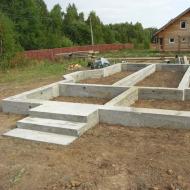
I will only say that the installation diagram of a solid fuel boiler implies a reinforced base for some models. This is not a separate foundation like for a brick heating stove; after all, not a single household TT boiler weighs 5-7 tons.

But a heat generator weighing 300-450 kilograms can no longer be simply placed on the floor along wooden joists in any room of a residential building. And that’s exactly how much a good one weighs in its entirety – both the firebox and the fire-tube heat exchanger.
Moreover, large mines with a large volumetric firebox, for example, also weigh a lot, even steel ones.
So, regarding our question, let's look at connecting a solid fuel boiler using several options. The connection diagram for a solid fuel heating boiler to CO can be implemented in the following forms:
- TT boiler in an open heating system with EC and radiators.
- TT boiler in a closed heating system with a PC with radiators.
- TT boiler with heat accumulator in a closed system with a PC with radiators.
- TT boiler with heat accumulator in a closed system with a PC with heated floors.
- Combined diagram for connecting a solid fuel boiler in a heating system with radiators and heated floors.
Let's immediately say that any low-temperature heating systems, which include a system with a TP, will require additional devices that will be responsible for the safety of the system and for its trouble-free operation.

The piping of a solid fuel boiler will have to include the following additional elements:
- Thermal accumulator or buffer tank - they have different volumes.
- Three-way valve for a solid fuel boiler - allows for the addition of cold water.
- Mandatory thermostat in the control system of a solid fuel boiler.
If we talk about a simple heating system with radiators, then you can connect it directly, through the security group. However, in order to prevent the system from boiling and to mitigate surges during thermal expansion of the system when the boiler reaches full power, the piping circuit of the solid fuel boiler includes a buffer tank.
The buffer tank is not a heat accumulator. Although the heat accumulator can be used as a buffer tank. The buffer tank, also called a capacitive hydraulic separator, has a minimum volume selected on the basis that for every 1000 watts of boiler thermal power there are 10 liters of tank.

That is, on a 20 kW boiler you need to install a container with a volume of 200 liters. It will not work to use a buffer tank as a heat accumulator. The minimum volume of an effective heat accumulator for a small house starts from 800-1000 liters.
TT boiler piping diagram
Proper piping of a solid fuel boiler with your own hands can only be done if the rules for such work are fully observed. I already wrote about it - it has its own characteristics.
Let's start with the return, that is, with the entrance of cold water into the heat generator. A circulation pump is installed on the return line if a closed CO with forced circulation is used. The pump is placed precisely on the return line; it pumps water into the boiler. If the central heating unit is installed on the supply from the boiler, then it will not last long there.

Why? Because the coolant output from the boiler heat exchanger is high temperature.
If diesel or gas boilers output from 40 to 65 degrees, set by the boiler automation, then at the output of the boiler TT - from 60 to 90 degrees in normal mode.
The cold water supply pipe is connected to the boiler inlet pipe. It is usually located at the bottom of the boiler.
The hot water supply pipe from the boiler is connected to the boiler outlet. Typically this pipe is located at the top of the boiler. This arrangement allows the use of .

The hot water outlet pipe from the boiler has a normal temperature of 60 to 90 degrees Celsius. In abnormal mode, the pipe can have a superheated steam temperature of 105-110 degrees Celsius on the inner surface, and up to 200-350 degrees Celsius on the outer part near the boiler pipe - from the superheated boiler itself.
Therefore, it must be made of metal, preferably copper. Although a steel pipe will also cope with its duties properly.

The basic rule that is established by the piping diagram of a solid fuel boiler is that there should be no shut-off valves between the heating system and the expansion tank.
What is included in the boiler safety group
The safety group of a solid fuel boiler includes three elements:
- A pressure gauge showing the pressure in the system at the boiler outlet.
- Emergency pressure relief valve, set to the upper value of the permissible pressure in the CO.
- Automatic air vent.
For ease of use, the safety group pressure gauge has an additional manually installed arrow, which shows the limit of permissible coolant pressure in the heating system.
The emergency pressure relief valve is configured to release the coolant when the set pressure limit is exceeded. Typically, the operating pressure in the heating system is 1.5-2 atm, the relief valve is set to 3 atm.
The air vent removes air when the heating system is filled with coolant. When the operating level is reached, the air vent valve closes.

The safety group of a solid fuel boiler should be installed at the outlet of the boiler heater, at the hot water supply to the heating system. Only such a scheme for piping a solid fuel boiler using a safety group is correct.
It happened to me that it was installed on the return line of the heating system. In this case, the boiler could explode, the pipes of the heating system will melt, and the safety group will still not work.
Adding cold water to the heating system with a TT boiler
To mix cold water into the heating system, a three-way valve is used for a solid fuel boiler. This device allows you to maintain the set temperature in the following systems:
- Heating system with heat accumulator.
- Low temperature heating system with heated floors.
A three-way valve for a solid fuel boiler mixes cold water from the return into the hot water supply from the boiler, thereby regulating the overall supply temperature. If the supply temperature to the heated floors is set at 45 degrees Celsius, and at the outlet from the boiler, for example, 70 degrees Celsius, the three-way valve will mix hot water from the supply and cooled water from the return to the desired value.

To effectively use a three-way valve for a solid fuel boiler, you need to install it after the heat accumulator. In this case, the water will be heated in the heat accumulator, and the three-way valve will mix hot water from the heat accumulator with cold water from the return.
Solid fuel boiler wiring diagram:

More on this topic on our website:
-
The energy market has never been highly stable. Constant fluctuations in prices for major fuels such as oil and natural gas...
A good option is wood-gas combined heating boilers or two boilers, one of which runs on solid fuel and the other on gas.
Any of these two options makes it possible to obtain heat in the case when there is no firewood left in the firebox, but there is still gas in the cylinder. It is better to combine two different boilers because the network will work constantly, even if one of the devices breaks down. If the gas-wood device breaks down, the system stops working and the room will be cold.
Difficulties in using two boilers in one system
The main difficulty is that gas boilers for a private home must operate in a closed system, while the safest for solid fuel devices is an open one. is in demand because the boiler can heat water to 110 °C or more, raising the pressure above permissible limits.
It can be lowered by reducing the intensity of combustion. But the effect will be visible when the coals burn completely. Even when burning low, they are very hot and continue to heat the water, increasing the pressure.

In such a situation, you need to relieve pressure. Copes with this task open type expansion tank. When its volume is not enough, water is discharged into the sewer through a pipe installed between the tank and the sewer. This tank allows air to enter the coolant. This is bad for the internal elements of the gas boiler, pipes, etc. Solutions to the problem:
- A combination of a closed and open heating system using a heat accumulator.
- Organization of a closed system for a wood or pellet boiler using a special safety group. In this case, two units are connected in parallel and operate both in pairs and separately.
Read also: Advantages of the Popov boiler
Connection with heat accumulator
The idea of using a heat accumulator lies in the following nuances:
- A gas boiler receiving gas from a cylinder and heating devices form one closed system. It includes a heat accumulator.
- Gas-generating boilers using wood, coal or pellets are also connected to a heat accumulator. But the water heated by them gives off heat to the heat accumulator, and then it is transferred to the coolant, which circulates through a closed system.
To make such a harness with your own hands you need to have:
- Open expansion tank.
- A hose that will be located between the tank and the sewer.
- Shut-off valves (13 pcs).
- Circulation pump (2 pcs).
- Three-way valve.
- Filter for water purification.
- Pipes made of steel or polypropylene.
The circuit can operate in four modes:
- From a wood-burning boiler with degrees transferred through a heat accumulator.
- From the same boiler with bypass of the heat accumulator (the gas device will be turned off).
- From a gas boiler that can receive gas from a cylinder.
- From both boilers.
Organization of an open system with a heat accumulator
- Do-it-yourself installation of shut-off valves on two fittings of a wood-burning boiler.
- Connecting the expansion tank. It must be placed so that it is higher than all the trim elements. The pressure under which a solid fuel boiler supplies water often exceeds the pressure under which coolant is supplied from a gas boiler connected to the cylinder. To equalize these values, you need to correctly configure the open expansion tank.
- Installation of taps on the pipes of the heat accumulator.
- Connection and boiler with two pipes.
- Connecting two tubes to pipes located between the heat accumulator and the boiler. They are installed near the taps, which are located near the battery fittings, or at a short distance from the shut-off valves. Shut-off valves are mounted on these tubes. Thanks to these pipes, it will be possible to use a solid fuel boiler bypassing the heat accumulator.
- Jumper insert. It connects the supply and return pipes located between the wood-burning boiler for the home and the heat accumulator. This jumper is attached to the supply line by welding or using fittings, and to the return line using a three-way valve. A small circle is formed through which the coolant will circulate until it heats up to 60 °C. Afterwards, the water will move in a large circle through the heat accumulator.
- Connecting the filter and pump. Their mounted on the return line in the place between the three-way valve and the boiler heat exchanger pipe A. To do this, a U-shaped tube is connected in parallel to the line, in the middle of which there is a pump with a filter. There should be taps before and after these elements. This solution allows you to make a path along which the coolant will move in the event of a lack of electricity.
Read also: Solid fuel cast iron boiler
Closed system with heat accumulator
There is no need to connect a device similar to an expansion tank because the gas boiler connected to the network or cylinder already includes a diaphragm expansion tank and also a safety valve.

To make this diagram correctly, you need:
- Connect a tap and a pipe to the supply fitting of the gas device, which will be suitable for the heating radiators.
- Install a circulation pump on this pipe in front of the heating devices.
- Connect heating devices with your own hands.
- Take a pipe from them that will go to the boiler. At its end, at a short distance from the gas unit, which is powered by a gas cylinder, you need to install a shut-off valve.
- Connect two tubes to the supply and return lines, which will approach y. The first must be connected before the circulation pump, the second - immediately after the radiators. Shut-off valves are installed on both pipes. Two tubes are connected to these pipes, which were cut into the open system before entering and after leaving the heat accumulator.
Closed system with two boilers
This scheme provides parallel connection of two boilers. Particular attention is paid to group security. Instead of an open expansion tank, a closed membrane tank is installed in a special room.
The security group consists of:
- Air bleed valve.
- Safety valve to reduce pressure.
- Pressure gauge.
The binding is done according to the following scheme:
- Shut-off valves are installed at the outlets of the heat exchangers of both boilers.
- A security group is installed with your own hands on the supply line that departs from. The distance between it and the valve may be small.
- Connect the supply pipes of both boilers. In this case, before connecting, a jumper is inserted into the line that extends from the solid fuel boiler for the home (to organize a small circle). The insertion point can be located at a distance of 1-2 m from the boiler. A check flapper valve is installed at a short distance from the jumper. If the wood boiler stops working, the coolant under pressure created by the gas cylinder-operated unit will not be able to move along the supply line towards the solid fuel device.
- The supply line is connected to heating radiators located in different rooms and at different distances from each other.
- Install the return line. It should be located between the batteries and boilers. In one place it is divided into two pipes. One of them will fit the gas boiler. on her a spring return valve is installed in front of the unit. The other pipe must be suitable for the solid fuel boiler. The above jumper is connected to it. A three-way valve is used for connection.
- Before branching the return line, it is worth installing a membrane tank and a circulation pump.
Heat generators that draw energy from different types of solid fuel have their own operating characteristics that should be taken into account when connecting to the heating system. Therefore, the wiring diagram of a solid fuel boiler includes several mandatory elements and devices that ensure long-term operation of the unit and its protection in emergency situations.
Features of operation of solid fuel boilers
The process of burning wood or coal is somewhat more complicated than burning the same methane (natural gas). Methane is a simple inorganic compound that decomposes at high temperatures into carbon dioxide and water with some carbon monoxide. Wood and coal are complex organic substances that, when burned, form several substances and gases, some of which are aggressive. This leaves its mark on the longevity of the heat generator. Individual piping of solid fuel boilers is done in order to create an optimal operating mode and thereby extend their service life.
One of the features of the operation of water heating units that burn solid fuel appears after the firebox is ignited and reaches operating mode. If the installation of heating pipelines is carried out directly to the heating installation and, during heating, cold water is passed through the water jacket of the unit, then condensation will begin to form intensively on the internal walls of the firebox. It reacts with combustion products, mixes with ash and firmly adheres to a metal or cast iron surface. The results are as follows:
- The steel walls of the combustion chamber are corroded by corrosion.
- A cast iron firebox is not as susceptible to corrosion, but its rough surface allows plaque to stick, which is very difficult to remove. The same coating will appear on the walls of the steel chamber.
To successfully combat condensate, it is necessary to install a small circulation circuit with a three-way valve; it is not recommended to connect a solid fuel boiler to the heating system directly.
There is one exception to the rule - when connecting the heat generator to a gravity heating system operating without a circulation pump, installation can be carried out directly. The coolant here flows according to the principle of convection, increasing its speed as it warms up, and condensation does not appear. True, this is only possible with low power heating equipment and in small houses.
Another feature of the operation of wood heating systems is inertia. When the water temperature in the system is sufficient, the automation closes the access of air to the firebox and stops the process. Nevertheless, combustion continues for some time, the coolant temperature exceeds the set one. The same phenomenon is observed when the circulation pump stops as a result of a power outage. Water in the jacket can boil, forming steam, and destroy the jacket or rupture pipes. To avoid this, a safety group with a relief valve set to a certain critical pressure is installed on the supply pipe or directly in the boiler water tank.
Connection diagram to the heating system
Below is a detailed typical piping of a solid fuel boiler with polypropylene with a small circuit and a mixing unit.

The purpose of the mixing unit is to prevent cold water from leaking from the return pipeline into the water jacket of the heat generator. A three-way valve, set to a temperature of at least 45º, closes the movement of the coolant in a small circle until its temperature reaches the set value. The valve then mixes water from the system into the return line. In order to clean it from scale and sludge, a filter is placed in front of the three-way tap - a mud filter. In this case, it must be installed exactly in the position as shown in the diagram; vertical installation of the filter is a mistake.
Piping the boiler with a buffer tank
Many manufacturers strongly recommend using . A boiler buffer tank is used for the following reasons:
- When the air damper is closed in the chamber, wood smoldering occurs with insufficient oxygen, and this leads to an increase in the proportion of carbon monoxide (CO) in combustion products and increased environmental pollution. Therefore, a solid fuel boiler must operate at medium or full power, accumulating excess heat in the accumulator tank.
- After the firewood burns out and the firebox goes out, the energy contained in the storage tank will be enough to heat the house for some time. The duration of this period of time depends on the volume of the tank.
The figure shows a diagram of the piping of a solid fuel boiler with a battery tank, a small circulation circuit and two mixing units. The arrows on it show the coolant circulation.
 An alternative to the previous connection methods is to connect a solid fuel boiler with a buffer tank (hydraulic arrow). The connection diagram is somewhat reminiscent of the previous one, with the difference that the hydraulic arrow does not serve as a heat accumulator, but is intended for hydraulic separation of the boiler circuit with the rest of the heating branches. There can be many of the latter: radiator heating, heated floors, indirect water heating boiler for domestic hot water. In this case, the temperature of the coolant in each branch needs to be different. Below is a diagram of connecting a solid fuel boiler with a buffer tank and a distribution manifold to a boiler and radiator heating system.

1 – heat generator; 2 – temperature sensor; 3 – three-way valve of the boiler circuit; 4 – membrane expansion tank; 5 – buffer capacity; 6 – radiators; 7 – heating circuit circulation pump; 8 - three-way valve of the heating circuit; 9 – room thermostat; 10 – indirect heating boiler; 11 - circulation pump of the DHW heating circuit; 12 – security group.
Collaboration with electric boilers
Very often, wood or coal-fired water heaters become a second heating unit in a furnace room where there is already a gas or electric installation. They will need to be properly connected to each other in order to work together correctly, so that one unit supports the other. This is very convenient, for example, when all the coal in one of them burns out. Then the electric or gas water heater automatically turns on. A typical wiring diagram for a solid fuel boiler and an electric boiler is shown in the following figure. It is assumed that the electric heater has its own circulation pump built in.
Conclusion
The presented circuits are the most common due to their simplicity and reliability; in reality, there are many more different connection methods. It is better to choose the right one for yourself with the help of a specialist, taking into account all factors and wishes.
How efficiently and reliably the heating structure will function primarily depends on how correctly the solid fuel boiler with or without a water circuit is connected. But this is possible when the connection diagram for a solid fuel boiler is made professionally (read also: " "). If this type of water heating device is used, as can be seen in the photo, it only has an input and an output, to which the remaining elements of the circuit are connected.
To work for a long time with maximum efficiency,
The operating instructions specify a minimum temperature of 55°C at the outlet and 45°C at the inlet (return) of the boiler. If these conditions are not met, condensate, collecting on the walls, can destroy the unit. To avoid such problems, you will need a diagram for connecting a solid fuel heating boiler to the heating system.

The correct installation of the device is of no small importance, since it must be placed strictly vertically on a rigid base. To install the flooring, create a cement screed at least 5 centimeters thick with bedding of the same height. The expansion tank should be mounted at the highest point above the heating system; it is usually placed in the attic.
The boiler's chimney should be equipped with a valve made of stainless steel; at the bottom of it, a condensate collector should be installed (read: " "). To clean the channel from soot along its entire length, you can create easily accessible, small-sized hatches. If the soot removal pipe passes through an unheated room, it should be insulated and thereby extend its service life.

Experts categorically do not recommend operating these devices without a safety valve. You can also install a three-way boiler valve. It is necessary to study the instructions on how to properly connect a solid fuel boiler and how to operate it. The fact is that solid fuel units can only be used in conjunction with a water circuit with a pressure of 2 kg/cm², and the permissible temperature level should not exceed 90°C.
Connection diagrams for solid fuel boilers
There are many schemes for connecting TT boilers. Sometimes they are irreplaceable. In each individual case, the connection diagram of a solid fuel boiler to the heating system is selected individually.
- When making a solid fuel boiler with your own hands, the drawing should not be memorized at all. It will be enough to know the basic design of a solid fuel heat generator, as well as the pros and cons of such devices.
- When calculating an ideal heat supply scheme, it is necessary to best combine the operation of a solid fuel device with a tank that accumulates thermal energy. The fact is that during operation the temperature of the water heating device can fluctuate in the range from 60°C to 90°C, since it is not possible to maintain it at a constant temperature. Units operating using coal or wood are classified as inert devices. This is how they differ from gas, electric and diesel heat generating plants.
- If installed, the drawings do not always provide for the installation of a water pump that provides forced circulation of the coolant. This happens for a number of reasons, one of which is frequent voltage drops in the electrical network or the absence of power lines near the house. Due to not using a pump, the cost of heating equipment will be cheaper, but when installing the system, you will need to maintain a slope. Read also: "".
- When a solid fuel boiler is installed, the installation diagram must provide for the presence of safety lines between the boiler and the tank at the inlet and outlet pipes in the immediate vicinity of the water heater. In addition, the distance between the boiler and the expansion tank should be as short as possible. The insertion of safety valves or taps is not permitted in this area.
- If you look at any drawing of a solid fuel boiler with your own hands and the diagram of its installation in the heating system, you will see that the circulation pump should be installed on the return pipe, which is also called the return pipe, close to the heat generator. They act in such a way that if there is a failure in the power supply, the heat supply structure continues to function without a forced device. The circulation pump is installed along a bypass path and then, if necessary, it is disconnected from the network, and the bypass is closed with taps.
- When installing a heating system, experts advise installing a bypass, which is a jumper with a tap placed between the supply and return lines. It will be required to return excess amount of hot coolant from the radiator to the riser when it is changed using a thermostat. Read also: "
The installation of a heating system in a private house begins with the installation of a boiler. Many suburban communities do not have a natural gas pipeline. Instructions on how to properly connect a solid fuel boiler will alleviate this problem.
Necessary conditions for the correct connection of a solid fuel boiler to the heating system
- A separate room for the boiler room is selected. The area is about 7m2. A boiler room in a separate building is ideal. Loading fuel into the boiler room can be made easier. It is enough to install a so-called chute in the area of the receiving bunker on the outside where, for example, coal will be unloaded. Having unloaded the fuel into the receiving hopper, the coal is poured down the slope into the boiler room on its own.
- It is preferable to place the heating boiler below the 0 floor level. This boiler installation option ensures ideal circulation of coolant in the heating system without the use of a circulation pump.
- The base for the boiler must be made of a concrete pad with an even top layer. The thickness of the concrete screed is 10 cm. The area of the base under the boiler should be 20 cm larger than the dimensions of the connected boiler. On the furnace side 40-50 cm.
- According to SNiP standards and fire safety requirements, the distance between the boiler and the wall is 50 cm. From the side of the combustion opening, firebox, to the opposite wall the distance is at least 1.3 m.
- The installed heating boiler should not have gaps between the base and the body.
- The boiler must be connected to the heating system with a steel pipe at least 1 meter long at the inlet and outlet of the pipeline. It is incorrect to connect the boiler to the heating system with copper and polymer pipes.
Below is a diagram of the correct connection of a solid fuel boiler.
There are many connection methods. Let's consider one of the simple and reliable connection methods.
A safety group is installed from the boiler on the direct pipeline. After the safety group, a tee for the bypass is installed. Next, the supply is connected to the heating system wiring. Having given up its heat in the heating system, the coolant returns to the boiler through the return pipe. To avoid the main disease in the operation of solid fuel boilers, condensation, which negatively affects the integrity of the boiler, a thermostatic three-way valve is installed, connected to the return line on the bypass, set to a temperature of 50-60°C. When heated, the coolant circulates through a small circuit through a three-way valve. A temperature of 55°C prevents the formation of condensation on the inner walls of the boiler. A circulation pump is installed after the three-way thermostatic valve. As soon as the return temperature reaches 55°C, the three-way valve opens and the heated coolant flows into the heating circuit to the radiators.
Connecting a solid fuel boiler paired with a gas boiler, diagrams and features
The connection diagram for a solid fuel boiler in parallel with a gas boiler differs from the installation of two solid fuel boilers. The requirements for the boiler room, where the main condition is air exchange, also differ:
- The area of a boiler room with a gas boiler, as recommended by fire authorities and the gas service, is calculated as follows: 1 kW of power - 0.2 m 3 with a ceiling height of 2.5 m, but not less than 15 m 3.
- A boiler room with a gas boiler must be equipped with a window with a window, the size of which is 0.03 m2 per 1 m3 of room volume.
- The entrance door of the boiler room must open only to the street. The door width is at least 80cm.
Gas boilers are available in two versions. Floor and wall. The requirements for installing a floor-standing gas boiler are the same as for a solid fuel boiler. The length of the pipe connecting the chimney and the boiler is no more than 25 cm. If the boiler is coaxial, the pipe for removing combustion products is installed at an angle of -3°. In another option, a gas boiler requires a separate pipe made of ceramic or lined with stainless steel with a hatch to remove combustion products, and a tee with a tap to remove condensate is installed in the lower part of the pipe.
A gas and solid fuel boiler are connected in parallel to the heating system in several ways. The schemes are different, it is not necessary to know them all, it is enough to understand the features that must be taken into account when using this combination of boilers in relation to your premises:
- Use the heat exchanger effectively. It will separate the open and closed heating circuits. Connect the boiler to one of the circuits, and connect the second boiler to the second circuit. A solid fuel boiler, capable of raising the coolant temperature to 115°C, heats the secondary closed circuit to which the gas boiler is connected. The gas boiler is adjusted to a temperature of about 50-60°C. The main load will be taken on by the solid fuel boiler. As the fuel burns out, the gas boiler will automatically turn on, heating the secondary circuit of the heat exchanger. The secondary circuit is equipped with a diaphragm expander. A closed expansion tank protects radiators from excess pressure. With this configuration of a connected solid fuel boiler, it is possible to install an open expansion tank directly in the boiler room under the ceiling.
- The use of a hydraulic arrow for parallel connection of boilers is used mainly in houses with a large area. The operating principle of this system is as follows. The heating solid fuel boiler is installed first with a circulation pump, for example, 25/60 installed on the return pipe. An MD solenoid valve is mounted on the pipe between the boiler and the pump, which regulates the boiler circulation. Mandatory installation of a configured safety valve on the supply pipe. Shut-off valves are not installed on the supply side. The gas boiler is installed second. Through a tee, the boiler is connected through the supply pipe to the pipe from the solid fuel boiler and then connected to the hydraulic needle. Shut-off valves are not installed on the switch. On the second boiler, a pre-set safety valve is installed on the supply. A closed expansion tank is installed from the hydraulic needle on the return pipeline to the tee. Then, through a tee on the pipe, it is connected first to a gas boiler with the installation of a circulation pump of lower power than that of the first boiler. A valve without a servo drive is installed after the pump. Next, a solid fuel boiler is connected from the tee on the return pipeline. The use of a manifold after a hydraulic switch allows you to assemble several heating circuits with pump groups on each of them. Collectors make it possible to configure each circuit individually according to the loads on heating devices.
- Another method of parallel connection of boilers is when a solid fuel heating unit is installed first, a gas heating unit is installed second, and between them a check valve is installed on the supply pipeline, operating in the direction from the first heating unit. A bypass is installed in front of the check valve, connected to a three-way thermostatic valve set to a temperature of 55°C. Between the thermostatic valve and the boiler, a circulation pump of greater power than in a gas pump is installed on the return pipeline. The gas boiler is connected through a tee on the supply pipeline with a solid fuel boiler and then the supply pipeline goes to the radiators. The return pipeline from the radiators is first connected through a tee to the gas boiler. After the tee, it is necessary to install a spring check valve at the boiler. When both boilers are operating simultaneously, you need to adjust the temperature regime on the boilers. The gas boiler is adjusted to a temperature of 45°C. The solid fuel boiler is adjusted to a temperature of 75-80°C. Solid fuel will have priority. As the fuel burns and the temperature in the first boiler drops, the gas boiler will turn on automatically and maintain the set temperature in the house.
- Use of buffer capacity. The heat accumulator is a large steel thermally insulated container, the task of which is to retain the heated coolant from the boiler. The maximum load occurs during fuel combustion in a solid fuel boiler. For efficient operation of the heating system, the heat accumulator performs one of the main tasks. But there are big disadvantages in this scheme. It takes from 2 to 4 hours to heat the radiators to the desired temperature. This is where the gas boiler plays its main role. Let's look at the installation diagram. The solid fuel boiler is tied in the traditional way. A safety group is installed on the supply pipeline in front of the bypass. Then a bypass is installed through the tee. Next, the supply pipeline is connected to the storage tank. The bypass is connected to the return pipe through a thermostatic three-way valve set at 55°C. Then, a circulation pump is installed, running towards the boiler, and then the pipeline is connected to the boiler. A working circuit is created, and the coolant in the heat accumulator begins to gradually heat up. From the storage tank, the supply pipeline goes to the heating devices. A three-way valve is installed on it, going to the bypass. From the other outlet of the three-way valve, a circulation pump is mounted on the supply pipe.
After the pump, a check petal valve is installed, operating towards the radiators. Next, the supply from the gas boiler with the supply from the battery is connected through a tee. After completing this work, the direct pipeline is connected to the heating system distribution. From the heating system, the return pipeline is connected through a tee to the gas boiler with the obligatory installation of a spring check valve operating towards the gas boiler. A closed expansion tank is inserted in front of the tee to protect the heating system. After the tee, through which the gas boiler is connected via the return, the return pipeline goes to the heat accumulator and is connected to the bypass from the supply pipeline also through the tee. After connecting to the bypass line, the return pipeline is connected to the storage tank. This scheme allows you to quickly heat the heating system. Further operation of the system is designed to prioritize the operation of the solid fuel boiler.
Combined operation of a solid fuel boiler paired with an electric one
The connection diagram for a solid fuel boiler in parallel with an electric one is described in detail and in detail in the video:
Coordinated operation of solid fuel, gas and electric heating boilers
If desired, you can use a fairly simple connection diagram to combine the operation of 3 or more different types of heating boilers in addition to solid fuel, which still remains the most acceptable and economical in terms of consumption of heating resources.
Articles on the topic