Repair of LED lamps using examples. Drivers for LEDs: types, characteristics and criteria for selecting devices Why do you need an LED driver
Powerful LEDs in lighting devices are connected through electronic drivers that stabilize the current at their output.
Nowadays, so-called energy-saving fluorescent lamps (compact fluorescent lamps - CFLs) have become widespread. But over time, they fail. One of the causes of the malfunction is burnout of the lamp filament. Do not rush to dispose of such lamps because the electronic board contains many components that can be used in the future in other home-made devices. These are chokes, transistors, diodes, capacitors. Typically, these lamps have a functional electronic board, which makes it possible to use them as a power supply or driver for an LED. As a result, in this way we will get a free driver for connecting LEDs, which is even more interesting.
You can watch the process of making homemade products in the video:
List of tools and materials
-energy saving fluorescent lamp;
-screwdriver;
- soldering iron;
-tester;
-white LED 10W;
-enamel wire with a diameter of 0.4 mm;
-thermal paste;
- diodes of the HER, FR, UF brand for 1-2A
-desk lamp.
Step one. Disassembling the lamp.
We disassemble the energy-saving fluorescent lamp by carefully prying it off with a screwdriver. The lamp bulb cannot be broken as there is mercury vapor inside. We call the filament of the bulb with a tester. If at least one thread shows a break, then the bulb is faulty. If there is a working similar lamp, then you can connect the bulb from it to the electronic board being converted to make sure that it is working properly.

Step two. Remaking the electronic converter.
For the modification, I used a 20W lamp, the choke of which can withstand a load of up to 20 W. For a 10W LED this is enough. If you need to connect a more powerful load, you can use an electronic lamp converter board with the appropriate power, or change the inductor with a larger core.
It is also possible to power LEDs of lower power by selecting the required voltage by the number of turns on the inductor.
I mounted wire jumpers on the pins to connect the lamp filaments.


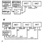
20 turns of enamel wire need to be wound over the primary winding of the inductor. Then we solder the secondary wound winding to the rectifier diode bridge. We connect 220V voltage to the lamp and measure the voltage at the output from the rectifier. It was 9.7V. An LED connected through an ammeter consumes a current of 0.83A. This LED has a rated current of 900mA, but in order to increase its service life, the current consumption is specially reduced. The diode bridge can be assembled on the board by surface mounting.
Diagram of the converted electronic converter board. As a result, from the inductor we get a transformer with a connected rectifier. Added components are shown in green.

Step three. Assembling an LED table lamp.
We remove the 220 volt lamp socket. I installed a 10W LED using thermal paste on a metal lampshade of an old table lamp. The table lamp shade serves as a heat sink for the LED.

The electronic power board and diode bridge were placed in the housing of the table lamp stand.
Many people quite often confuse power supplies and drivers, connecting LEDs and LED strips from the wrong sources.
As a result, after a short period of time they fail, and you have no idea what the reason was and begin to mistakenly blame the “low-quality” manufacturer.
Let's take a closer look at what their differences are and when you need to use one or another power source. But first, let's briefly look at the types of power supplies.
Transformer block
Today it is quite rare to see the use of a transformer power supply. The scheme of their assembly and operation is quite simple and understandable.
The most important element here is definitely the transformer. At home, it converts 220V voltage into 12 or 24V. That is, there is a direct conversion of one voltage to another. 
The network frequency is the usual 50 Hertz.
Next behind it is a rectifier. It rectifies a sinusoid of alternating voltage and produces a “constant” voltage at the output. That is, 12V supplied to the consumer is already a constant voltage of 12V, and not alternating. 
This scheme has 3 main advantages:
- its simplicity
- simplicity of design
- relative reliability
 However, there are also disadvantages here that made the developers think and come up with something more modern.
- firstly, it is heavy and has decent dimensions
- as a consequence of the first drawback - a large consumption of metal for assembling the entire structure
- Well, the whole thing is worsened by low cosine phi and low efficiency
This is why switching power supplies were invented. There is a slightly different operating principle here.
Switching power supplies
Firstly, voltage rectification occurs immediately. That is, AC 220V is supplied to the input and immediately converted to DC 220V at the input. 
Next is the pulse generator. Its main task is to create artificially alternating voltage with a very high frequency. Several tens or even hundreds of kilohertz (from 30 to 150 kHz). Compare this to the 50 Hz we are used to in home sockets. 
By the way, due to such a huge frequency, we practically do not hear the hum of pulse transformers. This is explained by the fact that the human ear is capable of distinguishing sound up to 20 kHz, no more. 
The third element in the circuit is a pulse transformer. It resembles a regular one in shape and design. However, its main difference is its small overall dimensions.
This is precisely what is achieved due to high frequency. 
Of these three elements, the most important is the pulse generator. Without it, there would not be such a relatively small power supply.
Advantages of pulse blocks:
- low price, if of course you compare it in terms of power, and the same unit assembled on a conventional transformer
- Efficiency from 90 to 98%
- supply voltage can be supplied in a wide range
- with a high-quality power supply manufacturer, switching UPSs have a higher cosine phi
 There are also disadvantages:
- complexity of the assembly diagram
- complex design
- If you come across a low-quality pulse unit, it will release a bunch of high-frequency interference into the network, which will affect the operation of other equipment
Simply put, a power supply, whether regular or switching, is a device with strictly one output voltage. Of course, it can be “twisted”, but not in large ranges.
Such blocks are not suitable for LED lamps. Therefore, drivers are used to power them.
What are the differences between a driver and a power supply?
Why can’t a simple power supply be used for LEDs, and why exactly is a driver needed? 
A driver is a device similar to a power supply.
However, as soon as you connect a load to it, it forces not the voltage, but the current to stabilize at one level!
LEDs are “powered” by electric current. They also have such a characteristic as voltage drop.
If you see the inscription 10mA and 2.7V on the LED, this means that the maximum permissible current for it is 10mA, no more.
When a current of this magnitude flows, the LED will lose 2.7 Volts. It will be lost, and not required for work. You will achieve current stabilization and the LED will work long and brightly. 
Moreover, LED is a semiconductor. And the resistance of this semiconductor depends on the voltage that is applied to it. The resistance changes according to the graph - the current-voltage characteristic. 
If you look at it, you can see that even if you do not increase or decrease the voltage much, it will dramatically change the current value several times over.
Moreover, the dependence is not directly proportional. 
It would seem that once you set the exact voltage, you can get the rated current that is required for the LED. At the same time, it will not exceed the limit values. It seems that a regular block should cope with this.
However, all LEDs have unique parameters and characteristics. At the same voltage, they can “eat” different currents. 
Moreover, these parameters can also change with changes in ambient temperature.
And the operating temperature range of LED lamps is very wide.
For example, in winter it can be -30 degrees outside, and in summer it’s already +40. And this is in the same place.
Therefore, if you connect such lamps from a regular switching power supply, and not from a driver, then their operating mode will be absolutely unpredictable.
Of course they will work, but in what light output mode and for how long is unknown. Such work always ends the same way - with the LED burning out. 
By the way, when the temperature rises, the luminous flux of LED lamps always drops, even for those connected via a driver. For low-quality specimens, the luminous flux drops very strongly, once they have been running for about an hour and warmed up.
For high-quality products, the luminous flux decreases slightly with heating, but still decreases. 
Therefore, after startup, each lamp must be given time so that it reaches its operating mode and the luminous flux stabilizes. Its change should be no more than 10% of the initial one.
Many unscrupulous manufacturers cheat and measure these parameters immediately after switching on, when the flow is still at its maximum.
If you need to connect several LEDs, then they are connected in series. This is necessary so that the same current flows through all the elements, despite their different current-voltage characteristics (volt-ampere characteristics). 
And this serial chain is connected to the driver. These chains can be combined in various ways. Create series-parallel or hybrid circuits. 
Driver Disadvantages
Of course, drivers also have their undeniable disadvantages:
- firstly, they are designed only for a certain current and power
This means that for each driver you will have to select a certain number of LEDs each time. If one of them accidentally fails during operation, the driver will send all the current to the remaining ones.
Which will lead to their overheating and subsequent burnout. That is, the loss of one LED entails a breakdown of the entire chain. 
There are also universal driver models, for them the number of LEDs is not important, the main thing is that their total power does not exceed the permissible limit. But they are much more expensive.
- highly specialized in LEDs
Simple power supplies can be used for various needs, wherever 12V or more is needed, for example for video surveillance systems. 
The main purpose of the drivers is LEDs.
Are there driverless factory lamps? Eat. Not long ago, many such LED lamps and spotlights appeared on the market. 
However, their energy efficiency is not very high, at the level of conventional fluorescent lamps. And how it will behave in the event of possible changes in parameters in our networks is a big question.
LED strips - connection from a power supply or driver?
A separate issue is LED strips. They do not require drivers at all, and as you know, they are connected from the usual 12-36 Volt power supplies. 
It would seem that there is a catch? There are also LEDs there.
But the fact is that the driver is already automatically present in the tape itself.
You have all seen soldered resistances (resistors) on LED strips. 
They are precisely responsible for limiting the current to the nominal value. One resistor is installed across three LEDs connected in series. 
Such sections of the tape, designed for a voltage of 12 Volts, are called clusters. These individual clusters are connected to each other in parallel throughout the entire length of the tape. 
And it is precisely thanks to this parallel connection that the same voltage of 12V is supplied to all LEDs. Thanks to clustering when installing the low-voltage strip, it can be easily cut into small pieces consisting of at least 3 LEDs.
It would seem that a solution has been found, but where is the drawback? And the main disadvantage of such a device is that these resistors do not do any useful work. 
They only additionally heat the surrounding space and the LED itself near it. This is why LED strips do not shine as brightly as we would like. As a result, they are used only as additional interior light.
Compare 60-70 lumens/watt for LED strips, versus 120-140 lumens/watt for lamps and driver-based solutions.
LEDs occupy the leading position among the most effective sources of artificial light today. This is largely due to the high-quality power sources for them. When working in conjunction with a properly selected driver, the LED will maintain stable light brightness for a long time, and the service life of the LED will be very, very long, measured in tens of thousands of hours.
Thus, a correctly selected driver for LEDs is the key to long and reliable operation of the light source. And in this article we will try to cover the topic of how to choose the right driver for an LED, what to look for, and what they generally are.
An LED driver is a stabilized constant voltage or constant current power source. In general, initially, an LED driver is a , but today even constant voltage sources for LEDs are called LED drivers. That is, we can say that the main condition is stable DC power characteristics.
An electronic device (essentially a stabilized pulse converter) is selected for the required load, be it a set of individual LEDs assembled in a series chain, or a parallel set of such chains, or maybe a strip or even one powerful LED.
A stabilized constant voltage power supply is well suited for LED strips, or for powering a set of several high-power LEDs connected one at a time in parallel - that is, when the rated voltage of the LED load is precisely known, and it is only necessary to select a power supply for the rated voltage at the corresponding maximum power .

Usually this does not cause problems, for example: 10 LEDs at 12 volts, 10 watts each, will require a 100 watt 12 volt power supply, rated for a maximum current of 8.3 amperes. All that remains is to adjust the output voltage using the adjusting resistor on the side, and you’re done.
For more complex LED assemblies, especially when several LEDs are connected in series, you need not just a power supply with a stabilized output voltage, but a full-fledged LED driver - an electronic device with a stabilized output current. Here, current is the main parameter, and the supply voltage of the LED assembly can automatically vary within certain limits.
For an even glow of the LED assembly, it is necessary to ensure the rated current through all the crystals, however, the voltage drop across the crystals may differ for different LEDs (since the I-V characteristics of each of the LEDs in the assembly are slightly different), so the voltage will not be the same on each LED, but the current should be the same.

LED drivers are produced mainly for power supply from a 220 volt network or from a 12 volt vehicle on-board network. The driver output parameters are specified in the form of voltage range and rated current.
For example, a driver with an output of 40-50 volts, 600 mA will allow you to connect four 12-volt LEDs with a power of 5-7 watts in series. Each LED will drop approximately 12 volts, the current through the series chain will be exactly 600 mA, while the voltage of 48 volts falls within the operating range of the driver.
A driver for LEDs with stabilized current is a universal power supply for LED assemblies, and its efficiency is quite high and here's why.
The power of the LED assembly is an important criterion, but what determines this load power? If the current were not stabilized, then a significant part of the power would be dissipated on the equalizing resistors of the assembly, that is, the efficiency would be low. But with a current-stabilized driver, equalizing resistors are not needed, and the resulting efficiency of the light source will be very high.
Drivers from different manufacturers differ in output power, protection class and used element base. As a rule, it is based on current output stabilization and protection against short circuit and overload.
Powered by 220 volt AC or 12 volt DC. The simplest compact drivers with low-voltage power supply can be implemented on a single universal chip, but their reliability, due to simplification, is lower. Nevertheless, such solutions are popular in auto tuning.

When choosing a driver for LEDs, you should understand that the use of resistors does not protect against interference, nor does the use of simplified circuits with quenching capacitors. Any voltage surges pass through resistors and capacitors, and the nonlinear I-V characteristic of the LED will certainly be reflected in the form of a current surge through the crystal, and this is harmful for the semiconductor. Linear stabilizers are also not the best option in terms of immunity to interference, and the efficiency of such solutions is lower.
It is best if the exact number, power, and switching circuit of the LEDs are known in advance, and all LEDs in the assembly will be the same model and from the same batch. Then select the driver.
The range of input voltages, output voltages, and rated current must be indicated on the case. Based on these parameters, a driver is selected. Pay attention to the protection class of the housing.
For research tasks, for example, packageless LED drivers are suitable; such models are widely represented on the market today. If you need to place the product in a housing, the user can make the housing independently.
Andrey Povny

Let's consider ways to connect medium-power ice diodes to the most popular ratings of 5V, 12 volts, 220V. Then they can be used in the manufacture of color and music devices, signal level indicators, smooth switching on and off. I’ve been planning to make a smooth artificial dawn for a long time in order to maintain my daily routine. In addition, dawn emulation allows you to wake up much better and easier.
Drivers with power supply from 5V to 30V

If you have a suitable power source from any household appliance, then it is better to use a low-voltage driver to turn it on. They can be up or down. A booster will make even 1.5V 5V so that the LED circuit works. A step-down from 10V-30V will make a lower one, for example 15V.
They are sold in a large variety by the Chinese; the low-voltage driver differs in two regulators from a simple Volt stabilizer.
The actual power of such a stabilizer will be lower than what the Chinese indicated. In the module parameters, they write the characteristics of the microcircuit and not the entire structure. If there is a large radiator, then such a module will handle 70% - 80% of what was promised. If there is no radiator, then 25% - 35%.

Particularly popular are models based on LM2596, which are already quite outdated due to low efficiency. They also get very hot, so without a cooling system they do not hold more than 1 Ampere.
XL4015, XL4005 are more efficient, the efficiency is much higher. Without a cooling radiator, they can withstand up to 2.5A. There are very miniature models based on MP1584 measuring 22mm by 17mm.
Turn on 1 diode

The most commonly used are 12 volts, 220 volts and 5V. This is how low-power LED lighting of 220V wall switches is made. Factory standard switches most often have a neon lamp installed.
Parallel connection

When connecting in parallel, it is advisable to use a separate resistor for each series circuit of diodes in order to obtain maximum reliability. Another option is to put one powerful resistor on several LEDs. But if one LED fails, the current on the remaining ones will increase. By whole it will be higher than the nominal or specified value, which will significantly reduce the resource and increase heating.
The rationality of using each method is calculated based on the requirements for the product.
Serial connection

Serial connection when powered from 220V is used in filament diodes and LED strips at 220 volts. In a long chain of 60-70 LEDs, each one drops 3V, which allows it to be connected directly to high voltage. Additionally, only a current rectifier is used to obtain plus and minus.
This connection is used in any lighting technology:
- LED lamps for home;
- led lamps;
- New Year's garlands for 220V;
- LED strips 220.
Lamps for the home usually use up to 20 LEDs connected in series; the voltage across them is about 60V. The maximum quantity is used in Chinese corn light bulbs, from 30 to 120 LED pieces. Corns do not have a protective flask, so the electrical contacts on which up to 180V are completely open.
Be careful if you see a long series string, and they are not always grounded. My neighbor grabbed the corn with his bare hands and then recited fascinating poems from bad words.
RGB LED connection

Low-power three-color RGB LEDs consist of three independent crystals located in one housing. If 3 crystals (red, green, blue) are turned on simultaneously, we get white light.
Each color is controlled independently of the others using an RGB controller. The control unit has ready-made programs and manual modes.
Turning on COB diodes

The connection diagrams are the same as for single-chip and three-color LEDs SMD5050, SMD 5630, SMD 5730. The only difference is that instead of 1 diode, a series circuit of several crystals is included.
Powerful LED matrices contain many crystals connected in series and in parallel. Therefore, power is required from 9 to 40 volts, depending on the power.
Connecting SMD5050 for 3 crystals

The SMD5050 differs from conventional diodes in that it consists of 3 white light crystals, and therefore has 6 legs. That is, it is equal to three SMD2835 made on the same crystals.
When connected in parallel using one resistor, reliability will be lower. If one of the crystals fails, the current through the remaining 2 increases. This leads to accelerated burnout of the remaining ones.
By using a separate resistance for each crystal, the above disadvantage is eliminated. But at the same time, the number of resistors used increases by 3 times and the LED connection circuit becomes more complex. Therefore, it is not used in LED strips and lamps.

LED strip 12V SMD5630

A clear example of connecting an LED to 12 volts is an LED strip. It consists of sections of 3 diodes and 1 resistor connected in series. Therefore, it can only be cut in the indicated places between these sections.

LED strip RGB 12V SMD5050

RGB tape uses three colors, each is controlled separately, and a resistor is installed for each color. You can cut only at the indicated location, so that each section has 3 SMD5050 and can be connected to 12 volts.

LED light sources are quickly gaining popularity and replacing uneconomical incandescent lamps and dangerous fluorescent analogues. They use energy efficiently, last a long time, and some of them can be repaired after failure.
To properly replace or repair a broken element, you will need an LED lamp circuit and knowledge of design features. And we examined this information in detail in our article, paying attention to the types of lamps and their design. We also provided a brief overview of the devices of the most popular LED models from well-known manufacturers.
A close acquaintance with the design of an LED lamp may be required only in one case - if it is necessary to repair or improve the light source.
Home craftsmen, having a set of elements on hand, can use LEDs, but a beginner cannot do it.
Considering that LED devices have become the basis of lighting systems for modern apartments, the ability to understand the structure of lamps and repair them can save a significant part of the family budget
But, having studied the circuit and having basic skills in working with electronics, even a beginner will be able to disassemble the lamp, replace broken parts, restoring the functionality of the device. To find detailed instructions for identifying a breakdown and self-repairing an LED lamp, please go to.
Does it make sense to repair an LED lamp? Undoubtedly. Unlike analogues with incandescent filaments for 10 rubles apiece, LED devices are expensive.
Let’s assume that a GAUSS “pear” costs about 80 rubles, and a better alternative OSRAM costs 120 rubles. Replacing a capacitor, resistor or diode will cost less, and the life of the lamp can be extended by timely replacement.
There are many modifications of LED lamps: candles, pears, balls, spotlights, capsules, strips, etc. They differ in shape, size and design. To clearly see the difference from an incandescent lamp, consider the common pear-shaped model.

Instead of a glass bulb there is a matte diffuser, the filament is replaced by “long-playing” diodes on the board, excess heat is removed by a radiator, and voltage stability is ensured by the driver
If you look away from the usual form, you can notice only one familiar element - . The size range of socles remains the same, so they fit traditional sockets and do not require changing the electrical system. But this is where the similarities end: the internal structure of LED devices is much more complex than that of incandescent lamps.
LED lamps are not designed to operate directly from a 220 V network, so a driver is located inside the device, which is both a power supply and control unit. It consists of many small elements, the main task of which is to rectify the current and reduce the voltage.
Types of schemes and their features
To create the optimal voltage for operation of the device, diodes are assembled based on a circuit with a capacitor or step-down transformer. The first option is cheaper, the second is used to equip high-power lamps.
There is a third type - inverter circuits, which are implemented either for assembling dimmable lamps, or for devices with a large number of diodes.
Option #1 - with capacitors to reduce voltage
Let's consider an example involving a capacitor, since such circuits are common in household lamps.
Elementary circuit of an LED lamp driver. The main elements that dampen the voltage are capacitors (C2, C3), but resistor R1 also performs the same function
Capacitor C1 protects against power line interference, and C4 smoothes out ripples. At the moment the current is supplied, two resistors - R2 and R3 - limit it and at the same time protect it from a short circuit, and the VD1 element converts alternating voltage.
When the current supply stops, the capacitor is discharged using resistor R4. By the way, R2, R3 and R4 are not used by all manufacturers of LED products.
Option #4 – Jazzway 7.5w GU10 lamp
The external elements of the lamp are easily detached, so you can get to the controller quickly enough by unscrewing two pairs of screws. The protective glass is held in place by latches. The board contains 17 diodes with serial communication.
However, the controller itself, located in the base, is generously filled with compound, and the wires are pressed into the terminals. To free them, you need to use a drill or use desoldering.
Conclusions and useful video on the topic
Homemade from scrap elements:
Nowadays, on commercial Internet sites you can purchase kits and individual elements for assembling lighting fixtures of various powers.
If desired, you can repair a failed LED lamp or modify a new one to get a better result. When purchasing, we recommend that you carefully check the characteristics and suitability of the parts.
Do you still have questions after reading the material above? Or do you want to add valuable information and other light bulb diagrams based on your personal experience in repairing LED lamps? Write your recommendations, add photos and diagrams, ask questions in the comments block below.
Articles on the topic