Universal milling machine 676 technical characteristics. Specialized milling machine SF676
The SF676 milling machine is a universal equipment that is capable of efficiently and quickly performing a number of related operations related to metalworking.
Milling machine SF676 – price and purpose
The SF676 universal milling machine has a low price and is famous for its high payback rates. We offer you the SF676 milling machine to buy in Moscow at a price of 650 thousand rubles. On the one hand, this is a considerable amount, but if you analyze the wide capabilities of the device, it will become clear that the benefits of purchasing it are obvious.
In addition, we are talking about some of the lowest prices on the market, since a universal professional milling machine in itself cannot be cheap.
Thus, the SF676 milling machine has the following purpose:
- The model can perform milling, drilling, boring, reaming, countersinking and slotting work.
- The machine is capable of milling both vertically and horizontally, as well as at various angles.
- The equipment can process workpieces horizontally using disk, cylindrical, shaped and other cutters, and vertically using face, key, end and other cutters.
- The machine allows simultaneous operation of horizontal and vertical spindles.
- The work involves small parts with a length of up to 0.8 m and a width of 0.25 m, and with certain equipment and large dimensions.
- The machine is capable of processing parts made of any metals, alloys, as well as other hard materials.
- The device finds its application in machine shops, as well as in tool, repair and experimental workshops.
- It is recommended to buy the SF676 machine for medium-scale, small-scale and individual production.
The high functionality of the model allows us to say that with proper loading, the SF676 milling machine with the specified price can quickly pay for itself and begin to bring tangible profits to its owners.
Milling machine SF676 – advantages
Buying a milling machine SF676 at our price means getting a universal type of specialized equipment that has the following advantages:
- Milling, drilling and other operations on the device are performed with increased accuracy (class H) and a high level of quality.
- Various cutting modes allow you to choose the most optimal option for a particular operation.
- The performance of the electric pump from which the coolant is supplied is high.
- The unit provides economical processing of parts in terms of time and effort.
- Operating the machine is convenient, simple and safe.
- The model does not take up much space, so it requires very little space to operate.
- The machine does not require long and complex maintenance.
- The device is reliable in operation, rarely fails, and has a long term of impeccable service.
STK LLC offers to buy the SF676 milling machine in Moscow. We deliver throughout Russia. Our consultants are always ready to help with choosing the model that is most suitable for your production.
They can also explain how best to organize the operation of equipment to achieve the fastest possible return on investment. In addition, our specialists are ready to install the SF676 milling machine on site and provide training for your employees to operate the machine.
The milling machine model SF 676 is intended for horizontal milling of products using cylindrical, disk, shaped and other cutters; and vertical milling with face, end, key and other cutters at various angles.
The machine is intended for use in tool shops* and experimental shops, as well as in mechanical shops of small-scale and individual production.
The presence of a wide range of revolutions, mechanical and accelerated feeds ensures economical processing of various parts through the use of high cutting conditions and reduction of auxiliary time.
The machine can perform a variety of boring, drilling, marking and other operations with high precision, which can be achieved if the machine is installed in a room with a constant temperature of + 20 ° + 2 ° C and air humidity of 65 + 5% and if there are no heat sources near the machine .
The machine must not be installed in the same room as machines that operate abrasive tools.
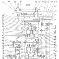
Kinematic diagram

The kinematic diagram consists of a main movement chain and a feed chain.
bed

An electric motor driving the main movement chain and the feed chain is mounted to the base (1) on the bracket (2). The transmission of rotation from the engine to the gearbox is carried out by three V-belts, the transmission of rotation from the gearbox - feeds to the caliper and spindle head mechanisms by two chain drives (sprockets 4, 6, 10, 11, 13,14).
To protect the feed mechanism of the caliper and spindle head from overload, there is a safety cam clutch (8).
The mechanical feed of the spindle headstock is turned on by a handle sitting on the shaft (16), the direction of movement of the headstock corresponds to the position of the handle. The mechanical feed of the spindle head can be automatically turned off by stops installed on it.
All rubbing surfaces are lubricated with ball lubricants using a syringe with CIATIM-201 lubricant.
Gearbox

The gear-type gearbox is assembled in a special housing, which is attached with a flange to the side of the station, and imparts 16 different speeds to the horizontal and vertical spindles by selective dialing.
The speed change is carried out by a switching mechanism located on the front wall of the box body as follows: the gear shift handle (4) must be lifted up. In this case, the disks (6) having a number of holes are separated. When turning the speed dial (1) and the associated disks, the position of the disk holes relative to the fingers (7) changes. This prepares for changing gears.
Moving the shift handle downwards brings the discs back to their original position. At the same time, the fingers, moving, shift the gearbox gears using levers.
When switching, there may be cases where the ends of the teeth of the meshed gears coincide. In this case, the discs do not align. In this case, it is necessary to turn shaft 1 with the flywheel (see Fig. 6).
To avoid gear damage, changing gears under load is prohibited.
Gearbox

The feed box provides the caliper and spindle head with 16 different feeds and rapid movements.
The feedbox shafts receive rotation from 1 gearbox shaft (see Fig. 6). The last (driven) shaft of the gearbox is connected to a roller on which two sprockets (10, 11) are placed (see Fig. 10), transmitting movement to the caliper and spindle mechanisms.
Changing the feed rate is carried out in the same way as changing the gearbox (see description of the mechanism for selecting speeds in the unit * Gearbox”).
When switching feeds, you must ensure* that the cross handle of the caliper is in the neutral position.
Accelerated movement is carried out by pressing the handle (7). When the handle is released, the working feed continues.
To ensure a constant direction of rotation of the gearbox gears when the gearbox is reversed, gear (9) is used, which automatically maintains the direction of rotation.
A piston pump (5) is used to lubricate the gears of the gearbox, feed box and spindle headstock. The pump piston (4) is driven in reciprocating motion by the eccentric gear (9). When the pump piston moves back and forth, oil is sucked from the frame reservoir and sprayed out. An oil mist is created, which lubricates all gears. To monitor the operation of the pump, a transparent eye (6) is installed on the feed box flange, through which the oil pulsation can be seen.
Caliper

The support carries the main table (9) of the machine with a vertical working plane and moves it in the vertical and horizontal directions.
The caliper consists of a housing (5) having vertical guides in the form of a “dovetail”
Moving along the guides of the frame, the support carries out vertical feeding of the table. Longitudinal feed is carried out by moving the table along the horizontal guides of the support.
The table feed control mechanism is located in the support body. The exercise mechanism is driven into rotation by the running shaft (4), which receives rotation from the feed box, and transmits rotation to the vertical (3) and horizontal (12) lead screws.
The feeds are controlled by a cross handle (17). The direction of movement coincides with the direction of movement of the cross handle.
In addition to mechanical feeding, the table can be moved manually; in the vertical direction with the flywheel (15), in the horizontal direction with the flywheel (14).
The table movements are counted using millimeter rulers, dials (vertical - dial (16), horizontal - dial (13) with a division of 0.005 mm), gauge blocks and indicators with a division of 0.01 mm.
The caliper has mechanisms for automatically switching off feeds. In the horizontal direction, pass-through and end stops (25) are used for this purpose. To automatically switch off the vertical feed, pass-through and end stops (3) (see Fig. 5) installed on the frame are used. The passage stops move in T-shaped slots and can be set to the required stroke size.
The caliper mechanisms are lubricated through a lubrication station. After pumping the lubrication station handle a few times, oil from the station reservoir is supplied through a feeder and distribution pipes to the caliper mechanisms. Lubrication should be carried out (by rocking the handle) only in the extreme left position of the corner horizontal table (or slide).
There are handles for clamping the caliper in the vertical (24) and horizontal (22) directions (see Fig. 5).
Headstock

The horizontal spindle (1) is mounted in a special housing (12), which moves along the frame guides, thereby providing transverse feed of the machine.
The spindle receives rotation from the gearbox through the intermediate drum gear (18), (see Fig. 11), mounted in the frame and the gear (9), sitting on the spindle.
The front support of the horizontal spindle is a double-row roller bearing (4) with a tapered bore. Axial loads are taken by thrust ball bearings (5). The middle and rear supports of the horizontal spindle are radial ball bearings (8,10), which simultaneously serve as gear supports (9).
The upper guides of the spindle head are designed for attaching the vertical head (Fig. 15) and the trunk (11). An earring (17) is attached to the trunk to support the mandrels. The vertical head, trunk and earring are clamped using crackers when screwing in the screws (10) (see Fig. 5) with an internal hexagon.
The tool is clamped in the horizontal spindle using a cleaning rod (13).
The amount of mechanical movement of the spindle head is set by intermediate stops (16).
The spindle head is moved by a screw (14) rigidly connected to it and a rotating nut (17) (see Fig. 10) fixed in the frame.
The design of the machine ensures the possibility of precise movements of the headstock for jig boring work. To do this, an indicator holder (18) is installed on the headstock, and a tile holder is attached to the frame, on which parallel measuring tiles are installed.
Vertical head

The vertical spindle is mounted in a special head with a trunk for mounting in the upper guides of the spindle head. The head, if necessary, can be rotated on the faceplate of the trunk (18) by ±90° from the vertical. Zeroing in the vertical position is fixed by two conical pins with a handle. The head is clamped to the trunk faceplate using hexagon socket bolts.
The vertical spindle (23) is mounted in a sleeve (5), which is moved manually in the housing (6) using a rack roller (24).
The sleeve is clamped with an asterisk handle (25), which has a hexagon for more reliable clamping.
The weight of the spindle is balanced by a helical leaf spring, one end of which is connected to a rack pinion. the other is with a vertical head housing.
The bevel gears of the head are supported by double radial bearings (10.17). Rotation of the spindle shank from the vertical bevel gear (9) is transmitted by splines. The horizontal bevel gear (19) receives rotation through splines from the horizontal shaft (20).
The lower support of the vertical spindle is a double-row roller bearing (3) with a tapered bore.
The upper support of the vertical spindle consists of two angular contact bearings (7), which also absorb axial loads.
The vertical head is lubricated daily using ball grease fittings (8,11). Labyrinth seals (1.13) protect against lubricant leakage and contamination.
Electrical diagram

By turning on the circuit breaker B1, voltage is supplied to the power circuit and the control circuit. The electric motor is turned on by button SB2, while the electric motor M1 is connected to the network through the contacts of the magnetic starter, the “start” button is blocked by the block contact of the magnetic starter. The microswitch of the B5 gearbox turns off the electric motor when the gears are turned on. The electric motor is turned off using button SB1
The spindle is reversed by reversing the electric motor through the packet switch VZ. When connecting the machine to the power supply, check that the spindle rotation direction corresponds to that indicated on the reverse packet switch plates.
The cooling pump is turned on and off by switch B2.
Switching on and off local lighting is done with switch B4.
Protection of the electrical equipment of the machine from short circuit currents and thermal protection of the electric motor is carried out by an automatic switch. Zero protection of the electric motor and electric pump - magnetic starter K.
The electrical equipment is made in accordance with the established requirements and has passed the test in accordance with the “Instructions for electrical equipment of metal-cutting machines.” The operation of electrical equipment must be carried out in accordance with the requirements of the “Rules for technical operation and safety of maintenance of industrial electrical installations.” enterprises."
The model 676 milling machine is designed for milling parts with different types of cutters. The cutters are used shaped, disk or cylindrical. They turn parts using a machine spindle whose axis is horizontal. It is also possible to turn parts using other cutters. These include end, key or end. This will involve a rotating spindle.
An important factor when choosing in favor of the SF 676 will be the permissibility of carrying out work with the synchronous activation of both spindles. In such circumstances, the machine will be able, in addition to milling, to perform countersinking, drilling, and boring.
Design features of the universal milling machine SF 676
In order to fully use the SF 676 milling machine with maximum benefit, you should remember the features of its design. To do this, it is necessary to ensure a constant air temperature of 20C in the room where the machine is located, as well as a relative air humidity of about 65%. In addition, there should be no devices nearby that generate heat energy or vibration pulses. The device has a fairly large scale of circulating reserves and shaft supply, rapid movements and even machine starts.
This functionality in the most favorable modes will be able to provide economical finishing of various kinds of workpieces.
The structure of the universal milling machine SF 676 includes the main sections, and they also determine its specifics. In addition, the equipment in question has a certain number of removable details and accessories; with the assistance of these, its operating resources are greatly increased. The body is fixed on a pedestal made of cast iron, on which, in turn, the fundamental units of the device are embedded. Boxes (feeds and speeds) are placed on the side of the bed.
Advantages
Thanks to its unique features, SF 676 has many advantages:
- Acceptability of milling parts of various sizes. Acceptable width is from 250 mm, and length up to 800 mm.
Availability of permissibility of chiselling procedures (the nozzle for chiselling is purchased separately); - The presence of a solid volumetric frame made of cast iron ensures vibration absorption and also preserves the properties of parts processed on the machine;
- Clear and convenient management of machine functions;
- Operation of SF 676 in mechanized and tool shops where single or small production is practiced;
- The likelihood of selecting optimal cutting systems due to the expanded circulation scale of both vertical and horizontal spindles;
- Introducing coolant using an electric pump. In this case, the pumping capacity will be at the level of 22 l/minute;
- Additional spindle head located on the retractable trunk.
This head has the ability to rotate at an angle of 90 degrees. Such rotations also occur in planes that are mutually perpendicular to each other.

Workspace size
The SF 676 kit includes two tables, both of which are functional. Each has individual dimensions and locations: for the vertical version: 630*250 mm, for the horizontal version – 800*250 mm.
Relatively compact volumes make it possible to use the router even in small spaces.
Performance is not affected in any way. Due to its dimensions - 120*124*105, as well as its weight - 1 ton, the machine does not use a large space for operation.

Components


General view of the machine and technical characteristics of the equipment in question
When classified, the milling machine received the “H” class, which indicates that the machine has normal accuracy. Shafts located in both planes are located in the spindle head. The shafts are connected to each other by a gear transmission. The diametric feed located in the spindle head produces transverse advance and is fixed on top of guides located horizontally.
This advancement activates the motor, using the feed box, as well as using the flywheel. The speed box has 16 modes. They communicate with both shafts. The speed varies from 50 to 1630 rpm and from 63 to 2040 rpm. SF 676 has an electric drive with a power of 3 kW, as well as an additional motor for the coolant supply system. This motor drives an electric pump.

The machine has the following engineering characteristics:
- Table dimensions: vertical: 630*250 mm, horizontal – 800*250 mm;
- The weight of workpieces during processing can reach up to 100 kg;
- Shaft offset from 125 to 375 mm;
- Number of revolutions – 16;
- The speed of the spindle head is from 13 to 395 m/mm;
- The highest frequency of shaft circulation: for the vertical one up to 2040 rpm, and for the horizontal one up to 1630 rpm;
- Length in the “table-shaft” direction from 80 to 450 mm;
- Cone standard 40AT5;
- Increased advancement of the spindle head along the X-Y axes: 300 – 380 mm, respectively.
- Description of the design of the wide-universal milling machine SF 676.
Controls
According to the specifications, if necessary, the machine can attach a vertical shaft to the face of the headstock. The machine support moves based on vertical guides. The machine has two work tables. A design feature of SF 676 will be the connection of a horizontal table located at the corner to its base plane. The corner table, in turn, has its own functionality for attaching and fixing parts that are to be processed on it.


The main electric motor contains a chain feed electric motor, as well as an electric motor for driving the main chain drive. An electric pump located at the base supplies cooling liquid. In this case, the electric pump itself is also used as a container for coolant. All electrical equipment is placed inside the frame, protected by covers.
Spindle speed box
The shafts of both positions receive 16 speeds from the gearbox using a selective dial. The transfer structure, which changes speeds, is located in front of the base of the box. This change occurs like this: the speed change knob is set to the maximum vertical position, thanks to this the discs with holes are separated. If you want to bring the disks to their initial position, lower the handle down.

Gearbox
The gear plays an important role in automatically maintaining the rotation path of the feed gears. This storage is carried out with the gearbox reverse engaged. This type of movement takes oil from the canister of the frame and then supplies it. The oil supply occurs in such small fractions and so intensely that the gears are lubricated by an oily haze. The movement of pulsating oil in a running pump can be monitored through a transparent insert located on the flange of the box.
Caliper
The support moves the main table with a fixed vertical working plane in both directions. The caliper body is a dovetail design. The table is fed in a vertical position thanks to movements using the bed guides. Longitudinal transmission is carried out only using horizontal guides. The support body hides a table feed manipulation device.
This control occurs at the speed of the drive shaft, which in turn receives movement thanks to the gearbox.
At the base of the support there is a device for influencing the table feed. This influence occurs due to the running shaft, during the action of the feed box. Next, the revolutions of the drive shaft are transmitted to the lead screws.

Headstock
The movement of the machine in the transverse direction is carried out by a horizontal shaft mounted in the base, and makes movement on the bases of the frame guides. The intermediate drum gear is engaged at shaft speeds. It itself is located in the frame and gear, which is mounted on the spindle. The mandrels are supported by an earring attached to the trunk. In addition, the design has a cleaning rod. Thanks to the cleaning rod, all the tools are clamped. Intermediate stops set the amount of automatic movement of the headstock.
Vertical head
The faceplate of the trunk contains a vertical head, which in turn has the ability to rotate up to 90 degrees from the vertical. The head can be installed with zero degrees of deflection, and it must be secured with two pins using hexagon socket bolts. The sleeve contains a vertical shaft. At the same time, it moves in the body manually.

The star-shaped handle, which secures the sleeve, is additionally equipped with a hexagon. Which leads to maximum clamping. To avoid distortion due to the weight of the spindle, a spiral spring made of a plate is installed. It is installed in such a way that one end is connected to the rack platen, and the other is attached to the head body. Double radial bearings provide a reliable support point for the head gears.
In this case, the splines transmit their rotation to the spindle shank. The bearing, which is a double-row roller bearing, supports the vertical spindle. The upper support of the vertical shaft is thrust bearings located along the radius. A special feature of these bearings is the perception of axial loads. Ball press-lubricators lubricate the vertical head every day.
Corner horizontal table
This object of consideration is cast from cast iron and bolted to the vertical surface of the main table. This fastening is facilitated by T-shaped grooves in the amount of three pieces.

Vise
This part is included in the specification for the machine as an integral part; it can rotate around its axis in a horizontal position without distance restrictions. In this case, the vice can be mounted on both tables.
Round table
This object of consideration is rotary and fixes the workpieces subject to the action of the milling cutter. In this case, the installation of this table is carried out on any of the plane directions of the table.

Slotting head
The cutter of this head is installed as part of a special housing. This housing also includes a trunk, which is designed to be fixed together with the cutter into the spindle head. The trunk has a unique design feature, which makes it possible to mount it in slotting and vertical heads.
Kinematic scheme


Modifications of the universal milling machine SF 676.
- 40AT5;
- KM4 – F2, containing 2 – coordinate DRO and cone KM4;
- 40AT5 – F2, containing 2 – coordinate DRO and cone 7:24 – 40;
- 40AT5 – F3, containing 3 – coordinate DRO and cone 7:24 – 40;

- KM4 – F3, containing a 3-coordinate DRO and a KM4 cone;
- L – lightweight, designed for mobile workshops.

In addition, the most compact model of the machine in question will be 676P. This model is distinguished by a slightly lighter weight of the machine itself and lower engine power. However, these features did not in any way affect the functional characteristics or performance.
Analogues of the universal milling machine SF – 676
- FCM250/676M;
- OMM64S, OMM67S;
- BM130;
- 6T80;
- X8132.
The SF-676 milling machine is a universal machine that is used in tool and repair shops at mechanical engineering enterprises. Mainly used for small-scale and individual production.
The highly versatile machine SF-676 allows you to perform all kinds of milling work.
In addition, it is suitable for marking, boring, drilling and other similar work.
It can process parts of the most complex configurations with extraordinary precision,
due to the fact that the machine can use a huge variety of tools and
devices.
| Prices for models of the universal milling machine SF676 | ||
| Machine SF-676-40AT5 |
modification of the machine cone 7:24-40 | RUB 970,500.00 |
| Machine SF-676-KM4 |
modification of the machine with a tool cone KM4 | RUB 991,200.00 |
| Machine SF-676F2-40AT5 |
modification of a machine with a 2-axis DRO with a cone 7:24-40 | 1103790.00 rub. |
| Machine SF-676F2-KM4 |
modification of a machine with a 2-axis digital display with a KM4 tool cone | RUB 1,128,900.00 |
| Machine SF-676F3-40AT5 |
modification of a machine with a 3-axis DRO with a cone 7:24-40 | 1216920.00 rub. |
| Machine SF-676F3-KM4 |
modification of a machine with a 3-axis digital display with a KM4 tool cone | 1241940.00 rub. |
| Removable table 7681К001-02 (300/5) |
Additional removable table 800x300 mm. 5 slots (replacement of standard table by agreement). | RUR 45,920.00 |
| The cost of replacing table 7681K001 with 7681K001-02 (300/5). | RUR 29,910.00 | |
Using SF676 you minimize auxiliary time, process parts
economical and efficient. All this is thanks to the technical characteristics of the device, a number of
revolutions, feeds and cutting modes.
The SF676 universal milling machine is designed for milling parts with cylindrical, disk and shaped cutters using a horizontal spindle, and face, end and key cutters using a rotating vertical spindle.
The machine can perform a number of milling and boring operations with high precision, which can be achieved if the machine is installed in a room with a constant temperature of 20±2°C and humidity of 65±5%, if there are no sources of heat or vibration near the machine. The machine can also perform drilling and reaming, chiselling, centering, counterbore, countersinking, reaming, boring.
The presence of two horizontal and rotary vertical spindles, as well as a large number of accessories for the machine, makes it highly versatile and convenient for working in tool shops of machine-building plants in the manufacture of fixtures, tools, relief dies and other products.
A wide range of spindle speeds and feeds, the presence of mechanical feeds and fast movements ensure economical processing of various parts in optimal conditions.
The machine is used in single and small-scale production in tool and mechanical shops of machine-building enterprises.
Machine accuracy class N.
Advantages of the SF676 metal milling machine
- The massive cast iron bed absorbs vibrations and allows you to maintain the quality of the parts processed on the machine.
- It is possible to mill both small parts and parts up to 800 mm long, 250 mm wide or more
- Use of the machine in tool and machine shops with small-scale and individual production
- The ability to perform slotting operations has been implemented (if you purchase a slotting head for an additional fee)
- Convenient (intuitive), classic machine control
- The small dimensions of the machine allow it to be placed in almost any room, including the garage
- A wide range of rotation of horizontal and vertical spindles allows you to select the most suitable cutting modes
- Coolant supply is carried out by an electric pump. Electric pump capacity 22 l/min
- The machine has an additional spindle (vertical) head located on a retractable trunk, which can be rotated at an angle of ±90 degrees in two mutually perpendicular planes.
Analogs of the cantilever milling machine SF-676
- FS-250, FSM-250/676M— Vladimir machine tool plant “Tekhnika” VSZ, Vladimir
- OMM64S, OMM67S— “Mikron”, Odessa
- VM130— Votkinsk Machine-Building Plant, Votkinsk
- DF-6725— Dmitrov Milling Machine Plant, Dmitrov
- VZ-371— VISAS, Vitebsk, Belarus
- 676, 67K25PM, 67K25PF1, 67K25PF2-0— Irkutsk Machine Tool Plant, Irkutsk
- 6T80— Chita Machine Tool Plant, Chita
- 675P, 6725PF1, 67E25PF1— Yerevan Milling Machine Plant, Yerevan, Armenia
- 676P, 67K25PR, 67K25PF1, 67K25PF2-0— Vilnius machine tool plant “Komunaras”, Vilnius (today Vingriai, JSC Vingriai, Lithuania
- X8132— Shandong Rooy Manufacture Co., Ltd., China
- JET UWF 401 DRO GELDMACHER— China
- JET JTM-1230W3— China
- FPS 300M- Germany
Description of the design of the SF-676 machine and its accessories
The universal milling machine SF 676 consists of main components (listed below), which organically determine its design, and a number of removable components and accessories, thanks to which its operational capabilities are significantly expanded
A frame is fixed to a cast iron base, on which all the main components of the machine are mounted.
Gear boxes and feed boxes are installed on the side of the frame.
In the upper part of the frame, along horizontal guides, a headstock with a horizontal spindle moves. If necessary, attach the head of a vertical spindle to the front end of the headstock.
The support moves along the vertical guides of the frame, and the table moves along the horizontal guides of the support.
A corner horizontal table is attached to the vertical (base) plane of the table, which serves for installation and fastening of the workpieces.
The electric motor driving the main movement chain and the feed chain is placed in the base. The coolant is supplied by an electric pump mounted on a base that doubles as a reservoir.
Electrical equipment is located under covers in the frame.
Location of controls for the SF-676 cantilever milling machine
- Electric pump switch
- Network switch
- Mechanical vertical feed shut-off stops
- Flywheel for manual movement of the table in the vertical direction
- Flywheel for manual movement of the table in the horizontal direction
- Handle for rapid movement of the caliper and spindle head
- Handle for turning on the horizontal and vertical mechanical feed of the table
- Speed dial
- Vertical spindle manual feed handle
- Screws for clamping the spindle headstock trunk and the vertical spindle trunk
- Tool clamp square in horizontal spindle
- Cooling tube clamp handle
- Light switch
- Mechanical cross feed cut-off stops
- Handwheel for manual spindle rotation
- Start and stop control buttons
- Gear knobs
- Feed switch handle
- Feed set disc
- Reversing the engine
- Mechanical longitudinal feed deflection stops
- Table clamp handle in horizontal direction
- Vertical spindle sleeve clamp handle
- Caliper clamp handle in vertical direction
- Headstock manual feed flywheel
- Headstock Clamp Handle
- Setting the vertical head to the zero position
- Handle for turning on the mechanical feed of the spindle head
- Vertical spindle movement limit stop
- Tool taper clamp square in vertical spindle
Spindle gearbox for machine SF-676
The gear-type gearbox is assembled in a special housing, which is attached with a flange to the side of the station, and imparts 16 different speeds to the horizontal and vertical spindles by selective dialing.
The speed change is carried out by a switching mechanism located on the front wall of the box body as follows: the gear shift handle (4) must be lifted up. In this case, the disks (6) having a number of holes are separated. When turning the speed dial (1) and the associated disks, the position of the disk holes relative to the fingers (7) changes. This prepares for changing gears.
Moving the shift handle downwards brings the discs back to their original position. At the same time, the fingers, moving, shift the gearbox gears using levers.
When switching, there may be cases where the ends of the teeth of the meshed gears coincide. In this case, the discs do not align. In this case, it is necessary to turn shaft 1 with the flywheel (see Fig. 6).
To avoid gear damage, changing gears under load is prohibited.
Feed box for milling machine SF-676
The feed box provides the caliper and spindle head with 16 different feeds and rapid movements.
The feedbox shafts receive rotation from 1 gearbox shaft (see Fig. 6). The last (driven) shaft of the gearbox is connected to a roller on which two sprockets (10, 11) are placed (see Fig. 10), transmitting movement to the caliper and spindle head mechanisms.
Changing the feed rate is done in the same way as changing the gearbox (see the description of the gearbox mechanism in the “Speedbox” unit).
When switching feeds, you must ensure that the cross handle of the caliper is in the neutral position.
Accelerated movement is carried out by pressing the handle (7). When the handle is released, the working feed continues.
To ensure a constant direction of rotation of the gearbox gears when the gearbox is reversed, gear (9) is used, which automatically maintains the direction of rotation.
A piston pump (5) is used to lubricate the gears of the gearbox, feed box and spindle headstock. The piston (4) of the pump is driven in reciprocating motion by the eccentric gear (9). When the pump piston moves back and forth, oil is sucked from the frame reservoir and sprayed out. An oil mist is created, which lubricates all gears. To monitor the operation of the pump, a transparent eye (6) is installed on the feed box flange, through which the oil pulsation can be seen.
Support for milling machine SF-676
The support carries the main table (9) of the machine with a vertical working plane and moves it in the vertical and horizontal directions.
The caliper consists of a housing (5) having vertical guides in the form of a “dovetail”
Moving along the guides of the frame, the support carries out vertical feeding of the table. Longitudinal feed is carried out by moving the table along the horizontal guides of the support.
The table feed control mechanism is located in the support body. The control mechanism is driven by the running shaft (4), which receives rotation from the feed box, and transmits rotation to the vertical (3) and horizontal (12) lead screws.
Spindle head of milling machine SF676
The horizontal spindle (1) is mounted in a special housing (12), which moves along the frame guides, thereby providing transverse feed of the machine.
The spindle receives rotation from the gearbox through the intermediate drum gear (18), (see Fig. 11), mounted in the frame and the gear (9), sitting on the spindle.
The upper guides of the spindle head are designed for attaching the vertical head (Fig. 15) and the trunk (11). An earring (17) is attached to the trunk to support the mandrels. The vertical head, trunk and earring are clamped using crackers when screwing in the screws (10) (see Fig. 5) with an internal hexagon.
The front support of the horizontal spindle is a double-row roller bearing (4) with a tapered bore. Axial loads are taken by thrust ball bearings (5). The middle and rear supports of the horizontal spindle are radial ball bearings (8,10), which simultaneously serve as gear supports (9).
The tool is clamped in the horizontal spindle using a cleaning rod (13).
The amount of mechanical movement of the spindle head is set by intermediate stops (16).
The spindle head is moved by a screw (14) rigidly connected to it and a rotating nut (17) (see Fig. 10) fixed in the frame.
The design of the machine ensures the possibility of precise movements of the headstock for jig boring work. To do this, an indicator holder (18) is installed on the headstock, and a tile holder is attached to the frame, on which tile-parallel measuring tiles are installed.
Vertical head of milling machine SF-676
The vertical spindle is mounted in a special head with a trunk for mounting in the upper guides of the spindle head. The head, if necessary, can be rotated on the faceplate of the trunk (18) ±90° from the vertical. Zero setting in a vertical position is fixed by two conical pins with a handle. The head is clamped to the trunk faceplate using hexagon socket bolts.
The vertical spindle (23) is mounted in a sleeve (5), which is moved manually in the housing (6) using a rack roller (24).
The sleeve is clamped with an asterisk handle (25), which has a hexagon for more reliable clamping.
The weight of the spindle is balanced by a helical leaf spring, one end of which is connected to the rack pinion, the other to the vertical head housing.
The bevel gears of the head are supported by double radial bearings (10.17). Rotation of the spindle shank from the vertical bevel gear (9) is transmitted by splines. The horizontal bevel gear (19) receives rotation through splines from the horizontal shaft (20).
The lower support of the vertical spindle is a double-row roller bearing (3) with a tapered hole.
The upper support of the vertical spindle consists of two angular contact bearings (7), which also absorb axial loads.
The vertical head is lubricated daily using ball grease fittings (8,11). Labyrinth seals (1.13) protect against lubricant leakage and contamination.
Corner horizontal table of the universal machine SF-676
The corner horizontal table is a cast iron casting and is attached to the vertical surface of the main table with bolts.
The horizontal plane of the table has three T-shaped grooves.
Vise
The vice is attached to the machine for fastening parts and has a rotation of 360 degrees in the horizontal plane. The vice can be installed both on a vertical table surface and on a horizontal one, as well as on a round table.
Round table
A manually driven round rotary table is designed for installing and securing parts during processing. The table can be installed both on the vertical surface of the main table and on the horizontal surface of the table.
Slotting head for machine SF 676
The slotter (3) of the slotting head is mounted in a special housing (5) with a trunk (9) for mounting in the upper guides of the spindle head.
The trunk is interchangeable and serves for installation in a vertical position of both vertical and slotting heads
We offer to buy a new universal milling machine SF676 at the price of the manufacturer.
Technical characteristics of the universal milling machine SF-676
| Parameter | Meaning |
| Distance from the axis of the horizontal spindle to the working surface of a corner horizontal table, mm: |
|
| least | 80 |
| greatest | 440 |
| Distance from the end of the vertical spindle to the working surface of a corner horizontal table, mm |
|
| least | 0 |
| greatest | 350 |
| Distance from the end of the horizontal spindle to the axis vertical spindle, mm |
115 |
| The greatest distance from the end of the horizontal spindle to the end of the shackle, mm |
315 |
| Taper of horizontal and vertical spindles | on request |
| Number of spindle speeds: | |
| horizontal | 16 |
| vertical | 16 |
| Spindle speed limits, rpm. | |
| horizontal | 50…1630 |
| vertical | 63…2040 |
| Number of table feeds | |
| longitudinal | 16 |
| vertical | 16 |
| Table feed limits, mm/min | |
| longitudinal | 13…395 |
| vertical | 13…395 |
| Accelerated table travel (longitudinal and vertical), mm/min. | 935 |
| Number of spindle head feeds | 16 |
| Spindle head feed limits, mm/min. | 13…395 |
| Accelerated speed of the spindle head, mm/min. | 935 |
| Maximum stroke of the spindle head, mm | 300 |
| Maximum axial movement of the vertical spindle, mm | 80 |
| Maximum rotation angle of the vertical spindle in the vertical plane, deg. |
±90 |
| Limb division price, mm | 0,05 |
| Rule division price, mm | 1 |
| Overall dimensions of the machine, mm | |
| length | 1200 |
| width | 1240 |
| height | 1780 |
| Weight of the SF676 machine, kg | 1050 |
| Characteristics of electrical equipment | |
| Type of supply circuit current | alternating three-phase |
| Current frequency, Hz | 50 |
| Voltage, V | 380 |
| Number of motors on the machine | 2 |
| Power supply voltage, V | 380 |
| Control circuit voltage, V | 380 |
| Lighting circuit voltage, V | 24 |
| Drive motor | AIR 100S4U3 |
| execution | 1 M 1081 |
| power, kWt | 3 |
| rotation speed, rpm. | 1500 |
| Electric pump | P-0.25.M.10 |
| power, kWt | 0,12 |
| productivity, l/min. | 22 |
| rotation speed, rpm. | 2800 |
| Total power of all electric motors, kW | 3,12 |
Delivery set of milling machine SF-676
|
Designation |
Name |
Note |
|||||||
|
SF 676.00.000. |
|||||||||
|
Complete machine |
Spindle cone VShG/ShB KM4 |
||||||||
|
Spare parts |
|||||||||
|
Transfer cracker |
|||||||||
|
Tool |
|||||||||
|
Keys GOST 2839 |
Supplied in a separate place in the general packaging Supplied in a separate place in the general packaging |
||||||||
|
7811-0022 NS 1 |
|||||||||
|
7811-0024 NS 1 |
|||||||||
|
7811-0025 NS 1 |
|||||||||
|
7811-0043 NS 1 |
|||||||||
|
Keys GOST R50123 |
|||||||||
|
Keys GOST 16984 |
|||||||||
|
Screwdrivers GOST17199 |
|||||||||
|
Accessories |
|||||||||
|
Vertical head |
Installed on the machine |
||||||||
|
Corner table |
|||||||||
|
Horizontal trunk |
Enclosed in a separate place in the general packaging. |
||||||||
|
Mandrel f. 27 with stacked rings and bushing |
|||||||||
|
Lever |
|||||||||
|
Cleaning rod heads |
|||||||||
|
Headstock ramrod |
|||||||||
|
Dial indicator |
|||||||||
|
Set of clamping devices (50 or 58 pieces) |
|||||||||
|
NT40/ER32 (ER40) |
Collet chuck with a set of collets ER32 or ER40 (6 pcs.) |
||||||||
|
Cooling system |
Installed on the machine |
||||||||
|
Technical documentation |
|||||||||
|
SF676.00.000RE |
Milling machine RE. Blueprints. |
Supplied in a separate place in the general packaging |
|||||||
|
Acceptance certificate. |
|||||||||
For an additional fee (at the Customer’s request), the SF676 machine is equipped with additional equipment (rotary tables, yews, milling chucks, boring heads, etc.)
Payment, delivery of the SF-676 machine and warranty obligations
The price for the SF676 cantilever milling machine is indicated on our website including VAT for the standard delivery set.
It is not difficult to buy an SF-676 machine - just call the numbers below in your city.
The sale of the universal milling machine model SF-676 is carried out by our company with 100% advance payment if the equipment is in stock and 50% advance payment when the machine is put into production and payment of the remaining 50% after notification of its readiness for shipment. A different percentage and a different payment procedure may be agreed upon with a specialist from the sales department of our company.
Delivery of goods weighing less than 1 ton is carried out by transport companies LLC "Business Lines", LLC "PEK", "Baikal-Service", LLC "Zheldorekspeditsiya", etc.
Delivery of goods weighing more than 1 ton is carried out by the Buyer's or Supplier's vehicles, as well as by railway transport.
Transport costs for delivery of goods are paid by the Buyer, unless otherwise specified in the Delivery Agreement.
The warranty for the new universal milling machine SF-676 is 12 months.
The manufacturer reserves the right to change the standard configuration and place of production of the equipment without notice!
The SF676 machine allows you to perform various operations: milling flat and shaped planes, drilling, threading, centering, counterbore, boring, chiseling, marking and other types of work. The machine can process parts of the most complex configurations from various materials with high precision. The machine is used in single and small-scale production in tool and mechanical shops of machine-building enterprises.
The presence of two spindles, horizontal and rotary vertical, as well as a large number of accessories for the machine, makes it highly versatile and convenient for working in the manufacture of fixtures, tools, relief stamps and other products;
- The massive cast iron bed absorbs vibrations and allows you to maintain the quality of the parts processed on the machine. The frame guides are protected by a special corrugated casing that protects the frame from premature destruction;
- Convenient, intuitive, classic machine control;
- The small dimensions of the machine allow it to be placed in almost any room;
- A wide range of rotation of horizontal and vertical spindles allows you to select the most suitable cutting modes. Coolant supply to the cutting zone is carried out through a modular hinged tube;
- A wide range of spindle speeds and feeds, the presence of mechanical feeds and fast movements ensure economical processing of various parts in optimal modes;
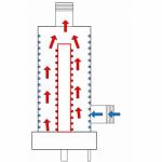
- The machine uses an original solution to the VFG design, based on the “DOUBLE CYLINDER” principle, which can be rotated at an angle of ±90 degrees. The “DOUBLE CYLINDER” design ensures stability of processing and safety of the body from destruction, allows for power milling;
- The machine uses industrial LED lighting; it is possible to install additional, more powerful, sealed lighting;
- The machine can be equipped with digital display units produced by SKB IS and produced by GIVI-Electonics. The DRO unit is equipped with a direct reference system, which displays the actual position or movement of the working unit in space, and not the rotation of the axis drive screw.
| PARAMETER | MEANING |
|---|---|
| Size of the working surface of the table, mm. | 630 x 250 (horizontal) 800 x 250 (vertical) |
| Maximum longitudinal movement of the table, mm. | 450 (X axis) |
| Maximum lateral movement of the spindle head, mm | 300 (Y axis) |
| Maximum vertical movement of the table, mm. | 380 (Z axis) |
| Distance from the axis of the horizontal spindle to the surface of the horizontal table, mm. | 80 - 440 (80 - 460 with the protective cover open) |
| Distance from the end of the vertical spindle to the surface of the horizontal table, mm. | 0-350 |
| Distance from the end of the horizontal spindle to the axis of the vertical spindle, mm | 115 |
| The greatest distance from the end of the horizontal spindle to the end of the shackle, mm | 315 |
| Spindle stroke, mm. | 60 (vertical head) |
| Spindle speed limits, rpm | 50-1630 (horizontal sp.); 63-2040 (vertical sp.) |
| Number of spindle speeds | 16 (horizontal) 16 (vertical) |
| Max. vertical rotation angle. heads, deg. | +/- 90 |
| Spindle end | 7:24-40 or KM4 |
| Spindle head feed limits, mm/min | 13…395 |
| Number of spindle head feeds | 16 |
| Limits of longitudinal and vertical table feeds (X, Y), mm/min | 13-395 |
| Number of table feeds | 16 |
| Speed of fast movements, m/min | 0.935 (X, Y axes) |
| Number of T-slots | 4 - horizontal table 2 - vertical table |
| T-slot width | 14N12 |
| Distance between the axes of T-slots, mm. | 50 (horizontal table) 80 (vertical table) |
| Main drive drive power, kW | 3 |
| Supply voltage, V | 380 |
| Accuracy class | H |
| Axial runout of horizontal/vertical spindles, µm, no more | 10 /15 |
| Flatness of working surfaces of vertical and corner horizontal tables at a length of 500 mm, no more | 20 |
| Radial runout of the conical surface of horizontal/vertical spindles, no more | 10 / 10 |
| Overall dimensions (LxBxH), mm. | 1200 x 1240 x 1780 (1400 x 1700 x 2100 per package) |
| Weight, kg. | 1050 (1600 per pack) |
BASIC DELIVERY SET:
- The machine is assembled;
- Tool kit;
- Set of crackers of 7 pcs.;
- 764К001.01-ДЦ Vertical head (removable unit);
- 676.60.001 Shield;
- 7681K001.01 (250/4) Standard corner table (removable unit);
- 766K012 Horizontal trunk (removable unit);
- 766K013 Earring (removable knot);
- Mandrel Ø27 with stacked rings and bushing;
- 676.83.000 Handle;
- cleaning rod of the head;
- Headstock ramrod;
- ICH-10 class 1 Dial indicator;
- Set of clamping devices (50 items);
- Collet chuck with a set of collets ER32 or ER40 (6 pcs.)
- Cooling system;
- SF676.00.000RE Milling machine RE. Blueprints.
ADDITIONAL EQUIPMENT:(supplied at extra cost)
- Vibration support OV-31M (4 pcs.);
- 7681K001-02 (300/5) Additional removable table 800 x 300 mm. 5 grooves;
- 7681K003G Additional globe table (installation in 3 planes);
- LED 24 - 5 CL Additional lighting (sealed);
- 6512-125,6582-2 Machine vice S=125mm, with a reinforced movable jaw and a closed screw with a rotary platform;
- UDG-D-160A Universal dividing head;
- Set of accessories for UDG-D-160A (rest, guitars, gear wheels, mandrel);
- 3-100.02.01 (Ch 7100-0002) Three-jaw lathe chuck Ø 100 mm;
- RKV 7205-4003 Horizontal-vertical rotary table Ø 250 mm;
- 61P-17-000 Round milling table Ø 250 mm;
- 7200-0215-02 Cast iron rotary machine vice (jaw width 160 mm);
- 7200-0215-05 Steel rotary machine vice (jaw width 160 mm);
- GD-1 Slotting head;
- NT40/KM2.3.4 Adapter sleeve for threaded tightening - 3 pcs.;
- NT40/KM2.3.4 Adapter sleeve for drill - 3 pcs.;
- NT40/ER32/40 Collet chuck with a set of collets Ø 32 mm. (18 pcs.);
- NT40-16/22/32315 Mandrel Ø16,22,32 with stacked rings and bushing;
- NT40/PSS16 Self-clamping drill chuck with NT40 mandrel;
- NT40/DCH Boring bar NT40 with a set of cutters;
- CR1 Lever center finder (with indicator).
Articles on the topic