Do-it-yourself security alarm. Simple Burglar Alarm Simulation in Proteus
Security alarm. Scheme
The alarm is made on a simple and affordable chip CD4023(or any other ... 4023), in which there are three logical elements "3I-NOT". Despite its simplicity, the alarm system has a quite good set of functions, and can compete with similar devices assembled on specialized microcircuits or microcontrollers. In addition, the use of simple "hard" logic makes the manufacture of alarms very simple and affordable, since no programming or search for expensive or rare microcircuits is required.
The alarm is designed to work with five contact sensors made from limit switches. One sensor - SD5 is specialized, it is installed on the front door. The other four can be installed on windows, shutters, other doors, hatches, manholes, etc. In the closed state, the contacts of the sensors are open, and close when the corresponding door, window, shutter, hatch, manhole, etc. is opened. That is, when it is closed, the limit switch stem is pressed, which means that its breaking contacts must be connected.
The alarm operation algorithm is as follows. Switching on is carried out by the power switch. The fact of switching on is indicated by one LED. After switching on, the alarm does not respond to sensors for about 15 seconds. However, during the first 2-3 seconds after the power is turned on, the circuit checks all sensors except the main door. If any of the sensors is closed (for example, the window is not closed), then a sound signal is heard for 2-3 seconds and the LED lights up, which points to a specific sensor that is in the closed state. If several sensors are closed, several LEDs will light up accordingly.
After fixing the problem, you need to turn on the alarm power again. Further, if all sensors are normal, only the LED indicating power on will light up. Approximately 15 seconds after the power is turned on, the alarm goes into armed mode. Now, if any of the sensors is closed (or several of them), the electronic block siren will turn on, which will sound for about 15 seconds. Then, the system will return to the armed mode and will wait for the next sensor to be triggered.
Disabling the alarm occurs in two stages. First, a code is entered using the keypad, after which the circuit is blocked for 15 seconds, during which it is possible to enter the premises and turn off the alarm with the power switch. If, however, you enter the premises and do not turn off the power of the alarm, then after 15 seconds it will enter the armed mode, and will work when you open the door or window, or something else that is under protection, even if you are inside the premises.
To set and dial the code, a simple electromechanical circuit of sequentially connected push-buttons is used. Such combination locks have been repeatedly described in this magazine, and despite such inconveniences as the need to simultaneously press the buttons of the code number, and the inability to change the code without parsing and soldering, they are very effective, cheap and
simple, which is also important.
The signaling device is an electronic siren for car alarms - today this is the most affordable signaling device.
Now about the scheme. The basis of the circuit is a three-input RS flip-flop on two elements of a D1 type 4023 chip.
There are two types of sensors. The main door door sensor is SD5, it is connected directly to pin 2 of D1.1. It is not checked by LED and beep at power up, because it is located on the main door that serves to exit the room, and the sensor check starts immediately after power is turned on, that is, while the person who turned on the power is still inside the room.
The remaining SD1-SD4 sensors are equipped with LEDs for status control and RC circuits that form a 2-3 second pulse when the sensor is closed.
Through decoupling diodes VD1-VD4 they are connected to pin 1 D1.1.
When the power is turned on, switch S10 starts charging capacitor C6 through resistor R11. With a capacitance of 10 uF and a resistance of 1 M, I got to unity for about 15 seconds, although both the accuracy of the capacitance of the capacitor and the amount of leakage play a role here, so the result may be different. Well, during this time, while C6 is charging through R11, there is a logic low voltage at pin 4 of D1.2. Therefore, the RS flip-flop D1.1-D1.2 is in a fixed position, and the output of D1.2 is a logical unit, regardless of what is at the inputs of the element D1.1. Therefore, during this time the trigger does not respond to sensors.
At the same time, if after turning on the power it turns out that one of the SD1-SD4 sensors is closed, then, for example, if it was SD1, the R2-C1 circuit will create a pulse lasting about 2-3 seconds, which will go to pin 11 D1 through the VD1 diode .3, and a high logic level will appear at its output for 2-3 seconds. Transistor key VT1-VT2 will open for 2-3 seconds and a short warning sound will sound. And the HL1 LED will light up, indicating that it is the SD1 sensor that is closed.
After charging C6, the circuit goes into protection mode. Now, when any of the sensors is triggered, the RS-trigger D1.1-D1.2 flips to zero at the output D1.2. At the same time, a high logic level is set at the output D1.3, and the transistors VT1-VT2 open, the BF1 siren sounds. But, this continues only as long as the capacitor C5 is charged through the resistor R12, that is, also about 15 seconds. Although, this time also depends on the actual capacitance of the capacitor C5 and the magnitude of its leakage current.
For the first stage of disabling the alarm, a keyboard of buttons S0-S9 is used (the buttons are numbered according to the inscriptions next to them on the dial pad). All switching buttons, without latching, are connected in series, but in such a way that the code number buttons are connected by normally open contacts, and all the others are connected by opening contacts. And this circuit is connected in parallel with C6. The circuit is closed only if only the buttons of the code number are pressed at the same time. At the same time, C6 is discharged, and the circuit goes into the state in which it is after turning on the power. That is, it does not respond to the door sensor SD5 for about 15 seconds.
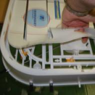
The assembly was carried out on a prototyping printed circuit board of industrial production.
The delay time after power on can be set by selecting R11 or C6. Siren sounding time - selection of R12 or C5.
A cell phone can also be attached to this system for remote signal transmission (L.1).
The peculiarity of this alarm is that it can be installed on a car, the front door of a room, a safe, and even on a closet without changing the circuit. The only difference is. what kind of load will be at the output and what kind of power source. And the modification is made by switching a miniature jumper in the connector installed on the signaling board. The alarm load can be a 12-volt car siren, an intermediate relay, or a miniature commercial or homemade siren.
And the functions of the sensor can be performed by a pair of reed switch-magnet, a closing or opening switch, automobile contact sensors, an explosive loop, a contact bookmark.
The schematic diagram of the basic version is shown in Figure 1. Such an alarm can work with one group of closing sensors (SD2) or one group of opening sensors (SD1). The choice of the type of sensors is carried out by changing the jumper N1 (in the diagram it is shown in the position of working with the closing sensor SD2, and the dotted line is for working with the opening sensor SD1).
If there are several closing sensors on the protected object, then they must be connected in parallel to each other, and if the sensors are opening, they must be connected in series.
Turn on the alarm with switch S1, through which power is supplied. Indicates the fact of turning on the LED HL1 of constant glow. After switching on, an exposure of several seconds is worked out, during which the alarm responds to the sensor triggering with a short beep. The value of this shutter speed is determined by the parameters of the RC circuit R3-C2.
Exposure is needed to exit the security facility, close the doors and check the operation of the sensors. At the end of the exposure, the alarm switches to the armed mode, which is indicated by the flashing LED HL2. Diode VD4 and resistor R5 stop shunting R6 and the duration of the alarm. depending on the rate of discharge of C3, increases.
Now, when the sensor is triggered, a positive pulse appears at the output D1.1, the duration of which depends on the parameters of the R2-C1 circuit. This pulse, through the diode VD3 and the current-limiting resistance R4, charges the capacitor C3 to a logic unit voltage. A negative pulse is formed at the output D1.2, the duration of which depends on the rate of discharge of the capacitor C3.
On the front of this pulse, a short pulse is generated by the C6-R8 circuit, which leads to a short-term appearance of a logical unit at the output D1 3. And this leads to a short-term activation of the BF1 siren. A short warning signal sounds, after which you have a few seconds to turn off the alarm with switch S1, which must be placed discreetly inside the protected object.
The duration of this delay depends on the parameters of the circuit R7-C4. If the alarm is not turned off within this delay, then the continuous alarm mode will be activated (the siren sounds for about 50 seconds).
The circuit then returns to guard mode. Capacitor C1 is necessary to prevent looping of the circuit in the case when, after intrusion on the object, the sensor remains in the triggered position
When installed on a vehicle, a standard industrial car alarm block siren is used as an alert device BF1. In this case, it is powered by a car battery, and it is more convenient to choose a closing sensor, because these are the door light switches, as well as automatic light switches under the hood and in the trunk.
If these sensors cannot be connected in parallel, they can be decoupled from each other by diodes of the KD522 type. By connecting these diodes with anodes to the VD2 anode, and connect their cathodes to the sensors.
When guarding the premises, it is more convenient to use an opening sensor, because these are the standard reed sensors installed on the door. If the sensor is homemade, then the choice of type depends on its design. The type of siren also depends on many factors. You can use the same car siren, or connect a more powerful siren powered by the mains, or a security call button through an intermediate relay.
However, you can additionally connect a relay to the siren to turn on the security call button. In this case, the relay winding is connected in parallel with the siren. In order not to damage the transistors of the output key (VT2 and VT3) by self-induction, it is necessary to turn on any diode in the reverse direction in parallel with the relay winding. The type of relay depends on the load, but the winding must be rated for 8-14V. The alarm supply voltage should be within the same limits.
Fig.2 Details are placed on a printed circuit board with one-sided arrangement of tracks. The wiring diagram and the layout of parts are given in Figure 2.
The method of manufacturing the board, - any available. The installation is loose, so the print can be drawn even with a sharpened match, dipped into bituminous varnish or nitro enamel as needed.
However, installation can be done on a breadboard printed circuit board or without a board at all, by gluing the microcircuits “upside down” to some kind of base, and making connections with mounting conductors and part leads.
The K561TL1 chip can be replaced with an analogue of the K1561 series or an imported CD4093. The K561TL1 chip contains four “2I-NOT” elements, with inputs made according to the Schmitt trigger circuit Pinout and the logic of operation is almost the same as that of the K561LA7, so you can try using the K561LA7 chip instead of the K561TL1, but only as a last resort, because the K561LA7 elements do not have inputs of Schmitt triggers, and the circuit will most likely work less stably and shutter speeds will not be worked out so clearly.
Transistors KT315 and KT815 are replaceable by any other general purpose transistors of the same power. Diodes can also be replaced by any analogues. LED NI - any indicator with a constant glow, and HL2 - flashing. The circuit shown in Figure 1 is the basic one. It uses only one chip with a low degree of integration, hence the limited functions.
Complicating it by adding another of the same microcircuit (Fig. 3), you can make a more universal signaling. In the circuit shown in Figure 3, there are two input channels (an additional channel is made on D2.1). This allows you to work simultaneously with two types of sensors - on one channel there can be a system of closing sensors, and on the second - opening sensors.
The K561LA7 chip (or its analogues K1561LA7, K176LA7, CD4011) contains four 2I-NOT logic elements (Fig. 1). The logic of the 2AND-NOT element is simple - if both of its inputs are logical units, then the output will be zero, and if this is not the case (that is, there is zero at one of the inputs or at both inputs), then the output will be one. The K561LA7 chip is CMOS logic, which means that its elements are made on field-effect transistors, so the input impedance of the K561LA7 is very high, and the power consumption from the power source is very low (this also applies to all other chips of the K561, K176, K1561 or CD40 series). Figure 2 shows a diagram of a simple time relay with indication on LEDs. The countdown starts at the moment the power is turned on by switch S1. At the very beginning, the capacitor C1 is discharged and the voltage across it is small (like a logical zero). Therefore, the output of D1.1 will be one, and the output of D1.2 will be zero. The HL2 LED will light up, and the HL1 LED will not light up. This will continue until C1 is charged through resistors R3 and R5 to a voltage that element D1.1 understands as a logical unit. At this moment, zero appears at the output of D1.1, and one at the output of D1.2.
Button S2 serves to restart the time relay (when you press it, it closes C1 and discharges it, and when you release it, C1 starts charging again). Thus, the countdown starts from the moment the power is turned on or from the moment the S2 button is pressed and released. The HL2 LED indicates that the countdown is in progress, and the HL1 LED indicates that the countdown is complete. And the time itself can be set with a variable resistor R3.
You can put a pen with a pointer and a scale on the shaft of the resistor R3, on which you can sign the time values by measuring them with a stopwatch. With the resistances of resistors R3 and R4 and capacitance C1 as in the diagram, you can set shutter speeds from a few seconds to a minute and a little more.
The circuit in Figure 2 uses only two IC elements, but it has two more. Using them, you can make it so that the time relay at the end of the exposure will give an audible signal.
 In Figure 3, a diagram of a time relay with sound. A multivibrator is made on elements D1 3 and D1.4, which generates pulses with a frequency of about 1000 Hz. This frequency depends on the resistance R5 and capacitor C2. Between the input and output of the D1.4 element, a piezoelectric “beeper” is connected, for example, from an electronic clock or a handset, a multimeter. When the multivibrator is running, it beeps.
You can control the multivibrator by changing the logic level at pin 12 D1.4. When zero is here, the multivibrator does not work, and the “tweeter” B1 is silent. When unit. - B1 beeps. This output (12) is connected to the output of the element D1.2. Therefore, the “beeper” beeps when HL2 goes out, that is, the sound alarm turns on immediately after the time relay has worked out the time interval.
If you do not have a piezoelectric "tweeter" instead, you can take, for example, a micro-speaker from an old receiver or headphones, a telephone set. But it must be connected through a transistor amplifier (Fig. 4), otherwise you can ruin the microcircuit.

However, if we do not need LED indication, we can again get by with only two elements. In Figure 5, a diagram of a time relay, in which there is only an audible alarm. While the capacitor C1 is discharged, the multivibrator is blocked by a logical zero and the "tweeter" is silent. And as soon as C1 is charged to the voltage of a logical unit, the multivibrator will work, and B1 will beep. Moreover, the tone of the sound and the frequency of the interruption can be adjusted. It can be used, for example, as a small siren or a house bell
A multivibrator is made on the elements D1 3 and D1.4. generating pulses of audio frequency, which are fed through an amplifier on a transistor VT5 to speaker B1. The tone of the sound depends on the frequency of these pulses, and their frequency can be adjusted by a variable resistor R4.

To interrupt the sound, a second multivibrator is used on the elements D1.1 and D1.2. It generates pulses of a much lower frequency. These pulses are sent to pin 12 D1 3. When the logical zero multivibrator D1.3-D1.4 is turned off here, the speaker is silent, and when it is one, a sound is heard. Thus, an intermittent sound is obtained, the tone of which can be adjusted by resistor R4, and the interruption frequency by R2. The volume of the sound largely depends on the speaker. And the speaker can be almost anything (for example, a speaker from a radio receiver, a telephone set, a radio point, or even an acoustic system from a music center).

Based on this siren, you can make a burglar alarm that will turn on every time someone opens the door to your room (Fig. 7).
Although it can be easily installed in .
The alarm scheme assumes the presence of one security circuit (with a delay for setting and triggering), but with a little refinement, it is quite possible to add as many instant trigger circuits as you like (connect glass break sensors, motion sensors, etc.). The advantage of this scheme is the ability to independently adjust the delay timers:
- Arming Delay- adjusting the time from the moment the system is turned on, until the moment when the owner of the apartment must leave the room and close the door, thereby closing the security circuit.
- Siren activation delay- Adjustment of the time from the moment the door is opened to the moment the acoustic howler system is turned on. That is, the time for which it is necessary to have time to enter the apartment and de-energize the alarm.
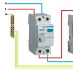
Let me emphasize again delay timers are adjusted independently and do not affect each other, as is often found in simple security systems based on logic chips. The circuit diagram of the alarm is shown in Figure No. 1. The circuit is implemented on 2 logic microcircuits: K561LA7 and K561LN2, which are powered by a 5 volt voltage regulator. The use of a stabilizer, of course, negates the advantages of the K561 series microcircuits, namely, the ultra-low current consumption, but eliminates the problem of changing the delay time when . The arming delay time depends on the value of the capacitor C1, the larger its capacity, the longer the delay period. The delay for turning on the siren is determined by the value of the capacitor C3, the larger its capacity, the more time it takes to turn off the security system after opening the contacts of the security loop.
Briefly about the principle of operation of the alarm:
First you need to consider a section of the circuit that is directly connected to the security loop.
 We are interested in one of the logical elements of the DD1 K561LA7 microcircuit, which is responsible for the operation of the system, namely, the transmission of a pulse for instantaneous charging of the capacitor C2 with a capacity of 2200 μF (which determines the time of the siren if the door is immediately closed after unauthorized entry, but the alarm remains on). Consider the processes that occur after the system has been triggered (i.e., after the instantaneous charging of the capacitor C2 2200 μF), in which case such a trigger occurs will be discussed later, so as not to get confused in what is happening. So, from the energy of C2 2200uF through the diode VD2 and the resistor R5 620k, a slow charge of the capacitor C3 200uF occurs. This stage is a delay for turning on the siren, as already mentioned, the higher the capacitance of C3, the more time will pass before turning on the siren. So, C3 is slowly charging, and at a certain moment, the voltage on the capacitor reaches a value (about 3 Volts), at which the inverters made on the DD2 K561LN2 chip are triggered. After a double inversion of the signal, from output No. 4 of the DD2 microcircuit, the supply voltage is supplied to the current-limiting resistor of the key, made on the KT819G bipolar transistor. This key "turns the ground", that is, when it is on, it passes current through itself and turns on the siren.

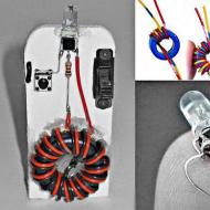
It remains for us to figure out how the arming delay works and under what circumstances the siren will turn on. So, when the security system is turned on, the capacitor C1 is slowly charged, which determines the arming delay time. When the voltage on the capacitor C1 is higher than the trigger threshold (about 3 volts), the output state of the first logic element of the DD1 K561LA7 microcircuit (leg 3 of the microcircuit) will change its state: immediately when turned on, this output of the microcircuit will have a voltage equal to the supply voltage, i.e. 5 volts, and with a charged capacitor C1 (at the end of the setting delay time) on this leg of the microcircuit, the voltage will become zero. We go further according to the scheme, the signal goes to the second logic element of the DD1 microcircuit, on which it is inverted. Simply put, if at the inputs of element No. 6, No. 5 there will be zero, then the output button (foot #4) appears. And vice versa, if both inputs(#6,#5) element will appear full supply voltage (5V), then at the output of the element the voltage will become zero. To reset the timers (in the case when, for some reason, you do not have time to go out and lock the door behind you), you must press the built-in switch without fixing the position (button) for a few seconds, which will discharge all time-setting capacitors through a nominal value of 5 ohms. Reset timers also necessary after each disarming of the alarm. You can combine the power off button and the reset button together if you find a suitable switch with a latching position and the ability to switch 4 pairs of contacts. There remains one last unanswered question.
We again return to the consideration of the logic element No. 3 of the DD1 K561LA7 microcircuit. As mentioned above, the signal inversion will occur when the supply voltage appears at both inputs of the logic element. That is, if there is +5 Volts at input No. 9 and input No. 8, the voltage at the output of this element (leg No. 10) will become zero. From output No. 10, the “zero” signal will be sent to exactly the same element, which also inverts the signal at the output of the last logic element of the DD1 K561LA7 chip, that is, +5 Volts will appear on leg No. 11, which will produce through the VD1 diode instant charging a 2200uF capacitor. What happens next has been described above.
So, the most important fragment of the description of the signaling action!
The security loop is normally closed, that is, in the “armed” mode, the button is closed, and in the door opening mode, the circuit opens. What does this give us, applicable to the scheme? The signal to trigger the siren, after a specified number of seconds, will be given only if the voltage at both inputs becomes 4-5 Volts. This can only happen if the security loop is open (in this case, 5 volts will be applied to input No. 8 through resistor R11 with a nominal value of 100k). And when a voltage of 5 Volts appears at input No. 9, and this will happen after the end of the arming delay time. Be sure to see more
PS / I tried to state the principle of operation of a homemade security alarm as concisely and accessible as possible, for understanding by novice homemade lovers. If you improve this model, please send a photo and a diagram of your version of the security alarm, I will be very grateful to you and post it in this section. Thank you in advance.
You can also send any my self-made designs, and I will be happy to post them on this site with your authorship! samodelkainfo(doggy) yandex.ru
Related Articles