Inverter circuit 12 220v clean.
Inverter 12 - 220v with a power of 500 watts: do it yourself: a diagram and a detailed description of the manufacture.
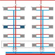
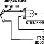
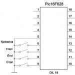
Scheme of a voltage converter (inverter) from 12 to 220 volts, for the operation of household appliances from a 12v battery.
The circuit is assembled on two microcircuits of the 155th series and six transistors. In the output stage, field-effect transistors are used, which have a very low resistance in the open state, which increases the efficiency of the converter and eliminates the need to install them on radiators of too large area.

On the D1 chip, a rectangular pulse generator is assembled, the repetition rate of which is about 200 Hz - diagram "A". From pin 8 of the microcircuit, the pulses go further to the frequency dividers assembled on the elements D2.1 - D2.2 of the D2 microcircuit. As a result, at pin 6 of the D2 microcircuit, the pulse repetition rate becomes half as much - 100 Hz - diagram "B", and at pin 8 the pulses become equal to a frequency of 50 Hz - diagram "C". Non-inverted pulses of 50 Hz are removed from pin 9 - diagram "D".
On the diodes VD1-VD2, an "OR" logic circuit is assembled. As a result, the pulses taken from the pins of the microcircuits D1 pin 8, D2 pin 6 form a pulse corresponding to the "E" diagram on the cathodes of the diodes. The cascade on transistors V1 and V2 serves to increase the amplitude of the pulses necessary for the full opening of the field-effect transistors. Transistors V3 and V4, connected to outputs 8 and 9 of the D2 chip, open in turn, thereby blocking one field-effect transistor V5, then another V6.
As a result, the control pulses are formed in such a way that there is a pause between them, which eliminates the possibility of through current flowing through the output transistors and significantly increases the efficiency. Diagrams "F" and "G" show the generated control pulses of transistors V5 and V6.
A correctly assembled converter starts working immediately after power is applied. When setting up, you should connect a frequency meter to the output of the device and set the frequency to 50-60 Hz by selecting resistor R1, and, if necessary, capacitor C1.

Transistors KT315 with any letter index, KT209 can be replaced with KT361 with any letter index. We will replace the voltage stabilizer KA7805 with the domestic KR142EN5A. Any resistors with a power of 0.125 ... 0.25 watts. Almost any low-frequency diodes, for example, KD105, IN4002.
Capacitor C1 type K73-11, K10-17V with low capacitance loss during heating. The transformer is taken from an old black-and-white tube TV, for example: "Spring", "Record". The winding for a voltage of 220 volts remains, and the remaining windings are removed. Two windings are wound over this winding with PEL wire - 2.1 mm. For better symmetry, they should be wound simultaneously in two wires. When connecting the windings, phasing should be taken into account.
Field-effect transistors are fixed through mica gaskets to a common aluminum radiator with a surface area of at least 600 sq.cm.


You can literally from improvised materials. Even blocks from a simple uninterruptible power supply can be taken as a basis - it is, in fact, a double converter - first, the voltage is reduced to 12 V to ensure battery charging.
And then the voltage is increased to 220 V, the current is converted from direct to alternating. Such devices can be used to power household equipment outside the home - drills, grinders, televisions, etc. It is not difficult to make such a device on your own, and its cost will be less than that of similar devices that are sold in stores.
The principle of operation of the inverter
The second name of the converter is the inverter. In fact, it is with pulse-width modulation type. Power is supplied from a 12 volt DC source (in this case, from a battery). At the output of the device, pulses appear, in which the duty cycle changes. Depends on the ratio of time during which there is or is no voltage. With a duty cycle equal to one, the maximum current value is output. As the duty cycle decreases, the current decreases.
The voltage at any time at the output is 220 V. Even the simplest 12V to 220V converter can operate in a wide frequency range - 50 kHz ... 5 MHz. It all depends on the specific scheme and the elements used in it. The voltage frequency is very high, it will be fatal for powering household equipment. To reduce it to the standard 50 Hz, it is necessary to use specially designed transformers. The PWM modulator allows you to create an alternating voltage from a constant voltage with the required frequency.
Feedback system
If the PWM modulator has no load, the duty cycle is at a minimum level, the voltage value is 220 V. As soon as the load is connected to the device, the current will increase sharply and the voltage will drop, it will be less than 220 V. If you decide to make a voltage converter from 12 to 220 volt with your own hands, then be sure to consider the presence of feedback. It allows you to compare the output voltage with a reference value.

If there is a difference in voltages, then a signal is sent to the generator, which allows you to increase the duty cycle of the pulses. With this system, it is possible to achieve maximum output power and a more stable voltage. As soon as the load is turned off, the voltage again jumps above 220 V - the feedback system fixes this and reduces the duty cycle value of the pulses. And so on until the tension is equalized.
Dealing with a dead battery
When the duty cycle and the value of the output current change, the load on the power source increases. This leads to its discharge and a decrease in voltage. And if a feedback system is used, it increases the duty cycle of the signals as much as possible, sometimes up to a maximum - one. Do-it-yourself 12/220 volt voltage converters without feedback react very strongly to dead batteries. During operation, the value of the output voltage is necessarily reduced.

If you plan to connect equipment such as angle grinders, electric lamps, boilers or kettles, then a decrease in voltage will not affect their operation. But in the event that the converter is needed to connect television equipment, laptops, computers, servers, amplifiers, feedback is simply necessary. It allows you to compensate for all power surges, which will ensure stable operation of devices.
Schema selection
To make a 12/220 V voltage converter with your own hands, you need to select a specific circuit. And be sure to consider the power of the devices that you plan to connect to it. Estimate approximately what load will be powered by the inverter. Be sure to add another 25% to the received power in reserve, it will not be superfluous. Based on the data obtained, you can choose a specific scheme. And, of course, one of the important points is

Assess your financial capabilities if you plan to purchase all components. And you will need a lot of expensive items. Fortunately, almost all of them are found in modern technology - in uninterruptible power supplies, power supplies for computers and laptops. By the way, a standard UPS can be used as a voltage converter, even no modifications are needed. Connect a more powerful battery to it and that's it. But you have to charge the battery from an additional power source - the standard one will not be able to generate the desired current value.
Elements of the converter circuit

The standard inverter design for converting 12 V DC to 220 AC consists of the following elements that can be found in any modern technology:
- PWM modulator - a special design microcontroller.
- Ferrite rings for the manufacture of high-frequency transformers.
- Power field effect transistors IGBT.
- electrolytic capacitors.
- Constant resistances of various power.
- Chokes for filtering current.
In the event that you are not confident in your own abilities, you can independently assemble the converter according to the multivibrator circuit. The transformer for such a device is suitable from a UPS or a power supply for transistor TVs. Such a device has one drawback - impressive dimensions. But it turns out to be much easier to set up than complex structures that work with high-frequency current.
Operation of inverters
If you decide to make a 12/220 voltage converter with your own hands according to a simple scheme, then its power may be low. But it is quite enough to power household equipment. But if the power is above 120 W, then the current consumption increases to 10 amperes at least. Therefore, when used in a car, it cannot be plugged into the cigarette lighter socket - all the wires will melt and the fuses will fail.

Therefore, car inverters with a power of more than 120 W must be connected to the battery using an additional fuse and relay. Be sure to lay the wire from the battery to the installation site of the car inverter. To turn on the converter, you can use a key switch or a button paired with an electromagnetic relay - it allows you to remove high current from the controls.
Comments (41):
#1 Snow White February 19 2015
Perfetto. Excellent This circuit seems to be what I was looking for about the transistor in a very interesting way. If we increase the number of turns, say three times, the current at KT 817 will also decrease to 0.6. He does not have enough speed is this the reason for the high current?
To be honest, I didn’t try to increase the turns. But what speed is not enough, yes, that’s why it was replaced by kt940. current can be further reduced. take only the lamp itself from the lamp and throw the board out of it. then the current lies within 0.3-0.35A ..
#3 Selyuk May 12 2015
Everything is very "simple", but where can I get transformer cups ??
#4 root May 12 2015
There is no gap between the ferrite cups in the design of the transformer of this high-voltage converter, so you can try using a ferrite ring or a frame from a pulse transformer with a ferrite core (you can take it from a non-working power supply from a computer).
You will need to experiment with the number of turns and the output voltage.
#5 pavel June 01 2015
And what is the principle of calculating the transformer and selecting transistors for this inverter? I would like to make one with a power supply of 60 volts.
The cups were taken because they simply were, and the number of turns in such a core is needed less. I have not tried ferrite rings, it works fine on a regular W-shaped ferrite. I don’t remember how many turns I wound, it’s like a primary - 12 turns with a 0.5 mm wire, and increasing just by eye, until the frame on the core is filled. The transformer was taken from a 4 by 5 cm monitor.
#7 Egor October 05 2015
I have a question for you, how much is the resistor on the left ohm at 220 ???
I'm just not very good at electronics.
#8 root October 05 2015
If there are only numbers near the resistor, then the resistance is in ohms. In the diagram, the resistor has a resistance of 220 ohms.
Tell me, is it possible to use your circuit to power the MTX-90 thyratron and not from 12, but from a 3.7 volt battery?
If possible, which transistors are better to take? The MTX-90 has a small operating current - from 2 to 7 mA, and the voltage for ignition needs about 170 volts, well, you can experiment with a transformer (about voltage).
I don't even know what to answer. Somehow I didn’t think about it .. And why do you need to feed the thyratron from this circuit? In principle, it will work, of course, the only question is how .. from 3.7 volts is also possible, but it is necessary to recalculate the windings or select them empirically.
#11 Oleg December 13 2015
People, tell me how to make an inverter from transistors from a Chinese typewriter on the control panel. Is it possible to put a ring ferrite core and is it possible to make a difference in turns by 3 times? I do this inverter for interest and to make it easier. And is it possible to put the voltage at the input somewhere around 3v?
Answer please! I will be glad if you answer all my questions! I'm waiting for your answers!
#12 Alexander December 17 2015
I have 30\10 ferrite cups, is it possible to wind a trance on them and how many turns should be wound, well, at least approximately.
#13 Alexander January 24 2016
Everything works great there, both a 15 watt lamp and a 20 watt lamp. You just need more powerful transistors. KT940 can not be touched, but 814 could be replaced at least with KT837. And if the current is high, you don’t need to rewind anything, you just need to increase the value of the resistor 3.1k. And the transformer is not necessarily of such dimensions, even a pulse from charging will work, transistors will still play a special role. p.s. These transistors have a power of no more than 10 watts.
#14 Eduard February 01 2016
What kind of transistor can replace kt814? Can it be 13005 or kt805?
#15 Alexander February 03 2016
Change it to kt805 - you’ll scrape off a lot of power, because kt805 can give up to 60 watts according to the datasheet
KT814 is p-n-p conductivity, and KT805 and 13005 are n-p-n ..., of course not Edward ...
#17 mar May 11 2016
instead of kt814 I put kt816,15W lamp pulled.
#18 sasha November 06 2016
put kt805 and kt837. primary 16v.0.5mm. secondary 230v. 0.3mm. lamp 23w. glow great.
#19 Edward November 19 2016
March. counter question, then how can you replace kt940, so that kt814 is replaced with kt805 or 13005 and change the polarity of the power supply? the primary is about 150-200 turns. if it is deployed as a booster and plugged into this circuit? I think it should work, but if you replace the bunch of kt814 and kt940 with something more modern, can you squeeze out up to 40 watts of power? I also want to try on the uc3845 PWM controller , there the circuit is generally primitive: a UC3845 microcircuit, in its circuit a frequency-setting resistor and a film capacitor, an IRFZ44 field-effect transistor and a transformer from an electronic transformer included in the circuit as a step-up, as a result we have up to 100 W of power at 12 volts
and why ".. 940 out in the old colors with a shaft .. everyone has nowhere to go ... replace with any reverse transistor, but you want 805, then yes .. 940 on direct conduction .... and change the polarity ... but again -why are there all such transactions in everyone's bins immeasurably ...
#21 pavel February 09 2017
why do you need to increase the power of the circuit :)? what, will you use KrAZ batteries (190 a / h) ?? this circuit makes sense, as the comrade correctly said, if you use a bulb from a lamp with a burnt circuit. otherwise, to hell with the button accordion: an LED lamp from the same battery, with the same light output, will enlighten many times longer! ..
#22 Pavel February 09 2017
now about transistors: you can change them, but you need to remember that any power transistor provides its declared power only when using an appropriate heat sink. this fact directly affects the dimensions of the entire device. and where do you get energy. l amp more powerful than 30 watts = 150? I haven't seen it for sale. and I already spoke about the battery for such a "pacifier" :). so, know the measure, inventors, good luck!
#23 Eduard February 24 2017
March, here I just have a problem with the Soviet kt940 and kt814. basically in my stocks are imported powerful high-frequency bipolar transistors 13005 for 5 amperes 400 volts, and the like. they managed to light the flask from 30 W of energy savings at full brightness, while the transistor was a little warm.
I would not argue that kt805 are buggy .. depending on which ones to use. unreliable in plastic, there is such a thing, and then for some 80 years. take 805 in metal, so just an indestructible transistor. however, it is necessary to emphasize the fact that they are buggy not because they are bad, but because they fell into not quite skillful hands, just
and you can put at least imported microwave transistors, it will work !!! verified!!. I did not pursue in this article to create a miniature lamp, but how to fit a burned-out lamp at minimal cost. to still serve
collector 814 should be grounded through a 10 microfarad capacitor, otherwise the surge is very large when switching.
814 transistor is in a half-open state - it needs a radiator, however.
it was easier to use a blocking generator.
what other capacitor is 10 microfarads, what kind of nonsense, is it really invisible from the photo that a miniature radiator will fit everything into a pack of cigarettes. and the blocking generator is not easier to use. You need at least three windings. and the transistor will heat up there no less !!!
#28 IamJiva August 14 2017
the blocking generator serves the same purpose, to carry out feedback (bring a microphone to the speaker so that it buzzes), if you do without a microphone - what for, you don’t need it, you managed here by adding a transistor, you can get by with one transistor in blocking, and turn the phase with turns of the winding, which (allow ) are independently connectable in either polarity. it is possible to squeeze out many watts but it is difficult, part of the energy (for powerful lamps is significant, up to 90%) is lost on the diode bridge and electrolyte (in the lamp rectifier) cheap (especially if powerful) and 50 Hz suitable, at 50 kHz smoke can already go from them and voltage will not appear to start the lamp, 50Hz diodes (simple, that is, not ultrafast and not Schottky) do not have time to lock up, and drain the charge back into the winding or somewhere else, from this the heating of everything and the incorrect operation of the generator, the electrolyte has an inductance (series) , and he only "recognizes" a short impulse, but is in no hurry to fulfill the order, waiting for the command to set aside ... the current begins to build up to infinity or how much they give, for 50Hz instantly, for 50kHz - never ... the transistor needs to be fast, it can warm up NO at the same time, IRF840 2pcs correctly used gave on 4 columns 4ohm 500wt each, 2000Wt power in class D powered by + -85V (170V) TL494 PWM, Ir2112 driver in the gates, 4pcs ultrafast diodes shunt the RF and IC, varistors 400V BC 30V RF
2 kW drum and bass power, they were a little warm on the same radiators as here, at the output of the choke from the TVS and 200 turns, at 2500wt they burned out without warning
it would be nice to shunt the primary with a diode, or better with a varistor, the output transformer of the primary (from flyback pulses possible in case of load disconnection, selection of transistors and turns of the primary for maximum efficiency here is also important and valuable as the ratio of sugar and vinegar with water + time on the timer in the microwave, so that get away and pull out the lollipops, the scheme works like a juggler that you have never seen, hope for the simplicity of transferring the ideal-harmony-efficiency-power to another circus and you don’t have to jacket
One question for the author. This converter will pull the electric shaver Kharkiv, Agidel, Berdsk, etc.
I need just such a miniature one that would always be built into a car for shaving.
Just do not write that the sale is full of electric shavers from batteries and clockwork. I am dear to me.
She's been with me for half my life.
Good luck.
#30 root January 21 2018
To power a 220V electric shaver from the on-board network of a car, it is better to assemble some kind of more reliable and powerful voltage converter. Here are some such schemes:
- Voltage inverter 12V to 220V from available parts (555, K561IE8, MJ3001)
- Simple voltage inverter 13V-220V for car (CD4093, IRF530)
Thanks for the links, but it's too expensive and difficult to assemble on the knee.
I don't have those details. But the old color.tel. and there is a tape recorder. It's all right there
People write that you can increase the power by replacing transistors with 805.837.
The electric shaver consumes 30 watts. It might pull. What do you think.
Fell into the hands of ROM Variom A.
The trouble is that the P216G transistors cannot be found now, namely one of them is not working. According to the parameters, the GT701A seems to be suitable, but here's how to determine the resistors. There are only 4 of them, two pairs. Just replacing both P216Gs with GT701A, I don’t think it will work. Tell.
#33 root February 05 2018
Agu1954, P216 transistors can be replaced with GT701A or P210V. Below are the main performance limits of these transistors:
- P216G: Ukb, max=50V; Ik max=7.5A; Pk max=24W; h21e>5; f gr.> 0.2 MHz;
- P210V: Ukb, max=45V; Ik max=12A; Pk max=45W; h21e>10; f gr.> 0.1 MHz;
- GT701A: Ukb, max=55V; Ik max=12A; Pk max=50W; h21e>10; f gr.=0.05 MHz;
Replace two P216 transistors with GT701A (P210V). For safety reasons, the first connection of the circuit to the battery should be made through a 3A fuse.
P.S. questions that are not related to the scheme that is given in the publication, please ask on the forum or in our social groups VK and FB.
#34 Sergey February 16 2018
#35 root February 16 2018
Hello Sergey. An old, and no longer working, postal address was indicated. Fixed it with a new one.
#36 Sergey February 16 2018
This converter operates at a frequency far greater than 50Hz. somewhere in the region of 20-50 kHz. even if you increase the power by replacing the transistors with more powerful ones, the razor will still not work. just physically the engine will not be able to operate at a frequency of tens of kilohertz
#38 Petro Kopitonenko November 19 2018
To reduce the frequency of the current on the converter, you must try to increase the number of turns of the transformer, both the primary winding and the secondary. What am I coming from. 50 hertz transformers have a large number of turns. And high-frequency - a small number of turns. This is the same as in oscillatory circuits, the frequency depends on the number of turns. I've soldered an experimental converter with a factory transformer at 50 hertz. There, two primary windings are wound with 40 turns instead of 10 turns according to the scheme. I heard the transformer buzzing at a frequency of about 40 hertz by ear. If it was a frequency of 50 kilohertz, I would not have heard anything!!!
#39 David June 13 2019
And you can use a ready-made transformer in this circuit. For example, a step-up transformer TP 30-2, just connect the other way around (to the output winding of 15 volts)
#40 root June 15 2019
The circuit needs a high-frequency transformer, TP 30-2 or another network one with W-like or toroidal iron will not work here.
#41 Dmitry October 06 2019
Good day! The primary of the transformer must be supplied with a snubber. You are practically engaged in switching the inductance with the second transistor. And don't care that the voltage is low! With a snubber chain, it will be easier for transistors. Someone above already suggested shunting the collector of the 814th with a capacity, but remained unheard. But better, of course, is a classic snubber - a diode, a resistor, a capacitor.
Buying a ready-made device will not be a problem- in car dealerships you can find (switching voltage converters) of various capacities and prices.
However, the price of such a medium power device (300-500 W) is several thousand rubles, and the reliability of many Chinese inverters is quite controversial. Making a simple converter with your own hands is not only a way to significantly save money, but also an opportunity to improve your knowledge in electronics. In case of failure, the repair of a home-made circuit will be significantly easier.
Simple pulse converter
The circuit of this device is very simple., and most of the parts can be removed from the computer's unnecessary power supply. Of course, it also has a noticeable drawback - the voltage of 220 volts obtained at the output of the transformer is far from sinusoidal in shape and has a frequency much higher than the accepted 50 Hz. Do not connect electric motors or sensitive electronics directly to it.

In order to be able to connect equipment containing switching power supplies to this inverter (for example, a laptop power supply), an interesting solution was applied - a rectifier with smoothing capacitors is installed at the output of the transformer. True, the connected adapter can work only in one position of the outlet, when the polarity of the output voltage matches the direction of the rectifier built into the adapter. Simple consumers such as incandescent lamps or a soldering iron can be connected directly to the output of the TR1 transformer.
The basis of the above circuit is the TL494 PWM controller, the most common in such devices. The frequency of the converter is set by the resistor R1 and the capacitor C2, their ratings can be taken slightly different from those indicated without a noticeable change in the operation of the circuit.
For greater efficiency, the converter circuit includes two arms on power field-effect transistors Q1 and Q2. These transistors must be placed on aluminum heatsinks, if you intend to use a common heatsink, install the transistors through insulating gaskets. Instead of those indicated on the IRFZ44 diagram, you can use IRFZ46 or IRFZ48 close in parameters.
The output inductor is wound on a ferrite ring from the inductor, also removed from the computer power supply. The primary winding is wound with a wire with a diameter of 0.6 mm and has 10 turns with a tap from the middle. A secondary winding containing 80 turns is wound on top of it. You can also take the output transformer from a broken uninterruptible power supply.
Read also: We talk about the device of the welding transformer
Instead of high-frequency diodes D1 and D2, you can take diodes of types FR107, FR207.
Since the circuit is very simple, after switching on, with proper installation, it will start working immediately and will not require any configuration. It will be able to deliver current up to 2.5 A to the load, but the optimal mode of operation will be a current of no more than 1.5 A - and this is more than 300 W of power.
Ready-made inverter of such power would cost about three or four thousand rubles.This scheme is made on domestic components and is quite old, but this does not make it less effective. Its main advantage is the output of a full-fledged alternating current with a voltage of 220 volts and a frequency of 50 Hz.

Here, the oscillation generator is made on a K561TM2 chip, which is a dual D-flip-flop. It is a complete analogue of the foreign CD4013 chip and can be replaced by it without changes in the circuit.
The converter also has two power arms on bipolar transistors KT827A. Their main drawback compared to modern field ones is a greater resistance in the open state, which is why they have stronger heating at the same switched power.
Since the inverter operates at low frequency, the transformer must have a powerful steel core. The author of the scheme suggests using the common Soviet network transformer TS-180.
Like other inverters based on simple PWM circuits, this converter has a voltage waveform quite different from the sinusoidal output, but this is somewhat smoothed out by the large inductance of the transformer windings and the output capacitor C7. Also, because of this, the transformer may emit a noticeable hum during operation - this is not a sign of a circuit malfunction.
A simple transistor inverter
This converter works on the same principle as the circuits listed above, but the rectangular pulse generator (multivibrator) in it is built on bipolar transistors.

The peculiarity of this circuit is that it remains operational even on a heavily discharged battery: the input voltage range is 3.5 ... 18 volts. But, since it lacks any stabilization of the output voltage, when the battery is discharged, the voltage at the load will also proportionally drop.
Since this circuit is also low-frequency, a transformer will be required similar to that used in the inverter based on K561TM2.
Inverter Circuit Improvements
The devices presented in the article are extremely simple and for a number of functions can't compare with factory counterparts. To improve their characteristics, you can resort to simple alterations, which, moreover, will allow you to better understand the principles of operation of pulse converters.
Read also: We make a semi-automatic welding machine with our own hands
Increasing output power
All the described devices work according to the same principle: through a key element (an output transistor of the shoulder), the primary winding of the transformer is connected to the power input for a time specified by the frequency and duty cycle of the master oscillator. In this case, magnetic field pulses are generated that excite common-mode pulses in the secondary winding of the transformer with a voltage equal to the voltage in the primary winding multiplied by the ratio of the number of turns in the windings.
Therefore, the current flowing through the output transistor is equal to the load current multiplied by the reciprocal of the turns ratio (transformation ratio). It is the maximum current that a transistor can pass through itself that determines the maximum power of the converter.
There are two ways to increase the power of the inverter: either use a more powerful transistor, or use the parallel connection of several less powerful transistors in one arm. For a home-made converter, the second method is preferable, since it allows not only the use of cheaper parts, but also keeps the converter working if one of the transistors fails. In the absence of built-in overload protection, such a solution will significantly increase the reliability of a home-made device. The heating of transistors will also decrease during their operation at the same load.
On the example of the last scheme, it will look like this:

Automatic shutdown when the battery is low
The absence in the converter circuit of a device that automatically turns it off when the supply voltage drops critically, can seriously let you down, if you leave such an inverter connected to the car battery. Supplementing a homemade inverter with automatic control will be extremely useful.
The simplest automatic load switch can be made from an automotive relay:

As you know, each relay has a certain voltage at which its contacts close. By selecting the resistance of the resistor R1 (it will be about 10% of the resistance of the relay winding), the moment is set when the relay breaks the contacts and stops supplying current to the inverter.
EXAMPLE: Take a relay with an operating voltage (U p) 9 volts and winding resistance (R o) 330 ohm. To make it work at a voltage above 11 volts (U min), in series with the winding, you need to turn on a resistor with resistanceR n, calculated from the condition of equalityU p /R o =(U min —U p) /R n. In our case, a 73 ohm resistor is required, the nearest standard value is 68 ohm.Of course, this device is extremely primitive and is more of a workout for the mind. For more stable operation, it must be supplemented with a simple control scheme that maintains the shutdown threshold much more accurately:

To connect household appliances to the on-board electrical system of a car, an inverter is required that can increase the voltage from 12 V to 220 V. They are available in sufficient quantities on store shelves, but their price is not encouraging. For those who are a little familiar with electrical engineering, it is possible to assemble a 12-220 volt voltage converter with their own hands. We will analyze two simple schemes.
Converters and their types
There are three types of 12-220 V converters. The first one is 220 V from 12 V. Such inverters are popular with motorists: you can connect standard devices through them - TVs, vacuum cleaners, etc. Reverse conversion - from 220 V to 12 - is required infrequently, usually in rooms with severe operating conditions (high humidity) to ensure electrical safety. For example, in steam rooms, pools or bathrooms. In order not to risk, the standard voltage of 220 V is reduced to 12 using the appropriate equipment.
The third option is, rather, a stabilizer based on two converters. First, the standard 220 V is converted to 12 V, then back to 220 V. This double conversion allows you to have an ideal sine wave at the output. Such devices are necessary for the normal operation of most electronically controlled household appliances. In any case, during installation, it is strongly advised to power it through such a converter - its electronics are very sensitive to the quality of the power supply, and replacing the control board costs about half the boiler.
Pulse converter 12-220V to 300 W
This circuit is simple, parts are available, most of them can be taken from a computer power supply or bought at any electronics store. The advantage of the circuit is the ease of implementation, the disadvantage is the non-ideal sine wave at the output and the frequency is higher than the standard 50 Hz. That is, devices requiring power supply cannot be connected to this converter. Not particularly sensitive devices can be connected directly to the output - incandescent lamps, an iron, a soldering iron, charging from a phone, etc.
The presented circuit in normal mode produces 1.5 A or pulls a load of 300 W, to a maximum of 2.5 A, but in this mode, transistors will noticeably heat up.

The circuit was built on the popular PWM controller TLT494. Field-effect transistors Q1 Q2 must be placed on radiators, preferably separate ones. When installing on a single radiator, lay an insulating gasket under the transistors. Instead of those indicated on the IRFZ244 diagram, you can use IRFZ46 or RFZ48 that are similar in characteristics.
The frequency in this 12 V to 220 V converter is set by resistor R1 and capacitor C2. The ratings may differ slightly from those indicated in the diagram. If you have an old non-working power supply for a computer, and it has a working output transformer, you can put it in the circuit. If the transformer is inoperative, remove the ferrite ring from it and wind the windings with a copper wire with a diameter of 0.6 mm. First, the primary winding is wound - 10 turns with a lead from the middle, then, on top - 80 turns of the secondary.
As already mentioned, such a 12-220 V voltage converter can only work with a load that is insensitive to power quality. In order to be able to connect more demanding devices, a rectifier is installed at the output, at the output of which the voltage is close to normal (diagram below).

The diagram shows high-frequency diodes of the HER307 type, but they can be replaced with the FR207 or FR107 series. Capacities are desirable to choose the specified value.
Chip Inverter
This 12-220 V voltage converter is assembled on the basis of a specialized KR1211EU1 microcircuit. This is a pulse generator that is taken from outputs 6 and 4. The pulses are antiphase, there is a small time gap between them - to prevent the simultaneous opening of both keys. The microcircuit is powered by a voltage of 9.5 V, which is set by a parametric stabilizer on a D814V zener diode.
Also in the circuit there are two field-effect transistors of increased power - IRL2505 (VT1 and VT2). They have a very low open output channel resistance - about 0.008 ohms, which is comparable to the resistance of a mechanical key. Permissible direct current - up to 104 A, pulsed - up to 360 A. Such characteristics really allow you to get 220 V at a load of up to 400 W. It is necessary to install transistors on radiators (with a power of up to 200 W, it is possible without them).

The pulse frequency depends on the parameters of the resistor R1 and the capacitor C1, a capacitor C6 is installed at the output to suppress high-frequency emissions.
It is better to take the transformer ready. In the circuit, it turns on the other way around - the low-voltage secondary winding serves as the primary, and the voltage is removed from the high-voltage secondary.
Possible replacements in the element base:
- The Zener diode D814V indicated in the circuit can be replaced by any one that produces 8-10 V. For example, KS 182, KS 191, KS 210.
- If there are no 1000 uF capacitors C4 and C5 of the K50-35 type, you can take four 5000 uF or 4700 uF capacitors and connect them in parallel,
- Instead of an imported capacitor C3 220m, you can put a domestic one of any type at 100-500 microfarads and a voltage of at least 10 V.
- Transformer - any with a power from 10 W to 1000 W, but its power must be at least twice the planned load.
When installing the circuits for connecting a transformer, transistors and connecting to a 12 V source, it is necessary to use large-section wires - the current here can reach high values (with a power of 400 W up to 40 A).
Pure sine inverter output
Converter circuits are complicated even for experienced radio amateurs, so making them yourself is not at all easy. An example of the simplest circuit is below.

In this case, it is easier to assemble a similar converter from ready-made boards. How - see the video.
The next video shows how to assemble a 220 volt converter with pure sine. Only the input voltage is not 12 V, but 24 V.
And this video just tells how you can change the input voltage, but get the required 220 V at the output.
Related Articles