Police quack (siren) on a PIC microcontroller. Police cracker (siren) on a PIC microcontroller How to make a DIY cracker out of paper
Before starting the article, I want to warn that the use of such signaling devices is illegal, at best, you face a tidy fine. VIP signals have always been considered a luxury item and there are many motorists who would like to have such a device in their car. This is a device that generates powerful low frequency audio signals.
The signal consists of three main parts.
1) Control panel - in new models, very often the entire generator circuit is located in the control panel. Such models as the right have only one MK, which is programmed and has several modes of operation.
2) Power amplifier - Amplifies the signal and feeds it to the emitter
3) Emitter - a loudspeaker that is designed to reproduce a signal.
The generator generates sawtooth pulses and feeds it to the preamplifier, then the signal from the preamplifier goes to the main power amplifier, in our case this amplifier is made on a cheap monophonic TDA2003 chip.
The circuit has a matching transformer, the signal from the UMZCH goes to the primary winding of this transformer. The secondary windings of the transformer are connected to the bases of powerful key transistors. The signal causes the transistors to open, the latter apply voltage to the primary winding of a more powerful (power) transformer.
At the output of this transformer, we already receive an amplified square-wave signal that is fed to the loudspeaker.
The generator (imitation of a cracker) is built on a two-channel pulse generator and divider counters. To simulate the sound of a siren, the circuit has a separate microcircuit.
The design scheme is available in the full archive, the download link of which you can find at the end of the article (free download).
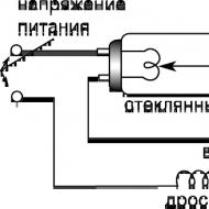
Once the author of these lines had to repair a Chinese-made scooter, brought by the “next generation” into a rather depressing appearance. In addition to many purely mechanical problems, on the scooter, in addition, there were also “electrical” problems - it must be that the young riders were not very interested in the technical condition of their “iron horse”, and therefore they rode with the voltage regulator “dead to zero” - in as a result, almost all the lamps on the machine turned out to be burned out, and the sound signal did not work.
How to make a cracker on a car
And if the regulator with light bulbs, after rummaging for a couple of hours in the garage, managed to get it, then with the search for a "pipe" the situation was a little more complicated - in a motorcycle store it cost, no more, no less, 400 rubles; and plus everything, at that time it was not on sale. The idea of putting an automobile “horn” on the scooter, after some thought, was also rejected - it has too much power - most likely, the weak button in the steering switch will not stand it and will start to burn, and then for some reason did not want to block the additional relay.
And the price of a car "horn" is considerable - even more than that of a motorcycle. This is where the idea was born to equip the scooter with some kind of self-made signal, while having a small manufacturing cost. Well, if you start a self-propelled gun, then let the result be interesting and unusual - it works, so to speak, on the image of a “moped”.
Since the life of this scooter was not easy, in the countryside - where traffic cops have not been seen since the time of Ivan Susanin, and absolutely quiet and sober shepherds (with their horned wards as interns) self-proclaimed road inspectors; an idea arose to equip the car with a signal resembling the famous “quack” - like the one that is installed on police cars and other emergency services - after all, in the village such a “little prank” most likely will not create any problems (unlike the city, where DPS, of course, will not allow such liberties - and rightly so, by the way!).
A run through amateur radio sites showed that “quacks” are, in principle, created by do-it-yourselfers; however, recently more and more of these devices are built on ... microcontrollers! To me, this approach seemed wasteful and not entirely justified - in fact, using MK for such things is the same as shooting sparrows from a cannon (although I myself actually know how to work with MK, and really love it). Therefore, it was decided to come up with the simplest and cheapest "quack" - such that everyone who is able to hold in their hands not only the steering wheel of their "cottage horse", but also a soldering iron, could easily repeat it. having a couple of hours of free time and a handful of cheap radio components.
But first, it was necessary to figure out what, after all, is that very “quacking” that is so unloved by the majority of traffic offenders? And since it was not possible to approach the police car with an oscilloscope and beep (at least without serious health consequences ©), I had to go the other way by installing a special program on my PC (Signal Generator from the WaveTools package - a generator of sound vibrations, with the ability to set their frequency and shape; the author of the program is Paul Kellett) in order to experiment a little and find the right sound by ear.
And now, after several hours of violence against one’s own ears, the secret finally became clear: the desired “quacking” is just asymmetric rectangular oscillations with a frequency of 80-90 Hz, having a duty cycle in the range from 3 to 12% - that is, in fact, an ordinary PWM signal. To the author of these lines, two options seemed closest to the "branded" ones (especially the first one): 80 Hz at 4%, and 85 Hz at 9%.
By the way, if the frequency of this signal is raised to 250-400 Hz. and make the fill factor equal to 15-30%, then the sound will become very similar to the sound of a standard car “beep”. This means that in order to “quack”, even the simplest PWM generator will be enough - if only it more or less accurately provides an audio signal with the specified characteristics at the output.
The diagram of the resulting device is shown in the figure - it is a classic asymmetric multivibrator loaded on a transistor switch, which is the simplest amplifier here. The ratings of the elements in this circuit are indicated for the 80 Hz / 4% mode. The frequency, as well as the duty cycle of the pulses at the output of such a generator, depend on the resistances R1 (sets the pulse duration), R2 (sets the pause duration) and capacitance C1. The calculation of the pulse duration is made according to the formula:
Timp. (sec)=0.8*С1 (uF)*R1 (kΩ)/1000; the duration of the pause is calculated in a similar way, but instead of the value of R1, it is necessary to substitute the value of R2. Accordingly, in order to calculate the resistance of the resistor R1 (or R2) for a predetermined value of the pulse (or pause) time, you need to use the formula inverse to the previous one:
R(kΩ)=Timp. (sec) / 0.8 * C1 (uF) * 1000. The duration of the pulse / pause (in seconds) can be calculated by setting the required frequency F (in Hz) and the duty cycle D (in percent), using the formulas:
Timp.=(1/(F*100))*D,
Tpause=(1/(F*100))*(100-D).
If, according to the results of calculations of the resistance of the resistors, they turn out to be very large (several MΩ), and there will not be any available (the author of these lines, for example, at first did exactly that), then you can simply increase the capacitance C1 by 5-10 times. and the resistance of the resistors, respectively, should be reduced by the same amount. It is also desirable to provide for the possibility of some frequency adjustment in the finished device. in order to achieve the most [unpleasant sound.
To do this, the capacitance of real C1 must be chosen somewhat less than the calculated one, and in parallel with it, turn on the "trimmer", which will, within small limits, "fit". The output transistor VT1, in principle, can also be used as a bipolar one, but still it is better to take the MIS - not necessarily the one indicated on the diagram (IRF610 was chosen only because it "came to hand") - almost any p- channel; the main thing is that it has an Imax of at least 1 A and a Umax of at least 30 V (applicable, for example, IRF610-640, IRF740, IRF3205 - as well as many others).
The thing here is that the transition resistance of a bipolar transistor, even if it is completely open in saturation mode, nevertheless has a fairly large value - sometimes it can exceed 10 ohms; but the active resistance of the load - a conventional dynamka - in this case is only 2-8 ohms. Thus, the transistor and its load form a kind of voltage divider, the resistance of the lower arm of which (transistor) can sometimes be two (or even more) times higher than the resistance of the upper arm (speaker).
As a result, the voltage drop across the transistor begins to exceed the voltage drop across the load, which in turn inevitably leads to a decrease in sound volume - after all, in fact, additional resistance of the transistor junction is connected in series with the speaker - the same 5-10 Ohms. Another thing is the key on the MIS transistor: in the open state, the resistance of its channel is less than an ohm (for some models, even hundredths of an ohm!) - that is, it is at the level of a conventional conductor; and this means that almost all the voltage applied to the load will fall on it - instead of wasting heat on the control transistor crystal.
If there is no opportunity (or desire) to use an MOS transistor, then a pair of bipolar ones will also fit - they need to be connected according to the Darlington circuit. The ideal sound emitter for this device could be a factory-made "bell" - like those installed at the station to notify passengers - of course, if it were found on sale more often and at an attractive price. However, you can do without any costs at all, using a conventional dynamic head as a sound emitter - it is desirable that it be larger and more powerful (although the author of these lines got good results with a simple two-watt “oval” from a “dead” Soviet radio receiver).
Moreover, this is almost the only case in radio electronics when the principle “the worse - the better” is completely justified: the speaker can be “hoarse”, have a torn diffuser - it’s checked, the “quacking” will not lose from this at all, and even vice versa - the sound will become more "juicy" and "evil". Sirens from car alarms also have a good sound (and even high mechanical strength - unlike flimsy speakers!)
You can buy a similar product for a penny - at the nearest car disassembly; then you will need to open the siren case, unsolder the standard “howl synthesizer” scarf from its sound emitter, and then connect the described device instead of the last one. Plus, the cases of most auto sirens are not only durable and sealed, but also very spacious, so that the entire “quack” circuit can be easily placed directly in such a case. The only limitation here is the fact that not all sirens reproduce low frequencies well.
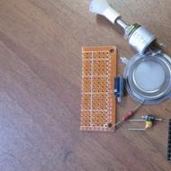
The printed circuit board for the device was not developed - in the author's version, the basis for all parts, except for the microcircuit, was a piece of foil fiberglass ~ 10 × 45 mm in size, with contact pads etched on it (if you don’t want to etch, you can simply cut them out with a scalpel or drill) ; then I soldered the microcircuit to this improvised scarf - with the usual mounting conductors on which it rests (it is also possible to assemble the device on a ready-made breadboard - “sieve”). After testing the design, a case about 45 mm long was made for it, cut out of a 40 × 40 mm plastic cable channel.
I made the channel cover longer than its U-shaped part by 20 mm in order to drill a hole for the fastening bolt in the resulting allowance. The result is a quite decent box with an "ear" - like a "nine" relay, only a little larger. To seal the case, a very reckless attempt was made to fill it with bitumen heated on a blowtorch, which is why the circuit safely went to its "electronic paradise" (do not repeat my mistakes!).
The second instance was more fortunate - it was decided to fill its body with transparent building silicone (which is sold in large syringes - “pistols”), and the “patient” courageously endured this “execution”. True, silicone has one significant drawback - in a relatively large volume of the case, it freezes extremely slowly, even if it is “dryed” on a battery; therefore, such a sealant will reach full polymerization only after a few weeks.
In the end, the cost of all this “tuning” turned out to be even lower than the 10 rubles indicated in the title of the article. - in fact, I had to buy only K176LA7 (~ 3 rubles, replaceable by K561LA7, K176 (561) LE5; and with a slight change in the scheme - also by K176 (561) LN2); all other details, including the output transistor and speaker, thanks to many years of "collecting and arguing" got me absolutely free.
The given device is useful not only as an original “horn” for a scooter or bicycle - it can also be successfully used as a howler in a security (or fire) alarm - the sound of a police car, which unexpectedly caught lovers of someone else's good by surprise, is likely to be to their liking ". And in agriculture, such a “quack” will help scare away uninvited guests - rodents, moles, birds, etc., from the long-awaited harvest - the author of these lines, for example, personally observed how the sound of this device scared away a whole brood of magpies.
In such cases, the logical elements D1.3-D1.4, which remained unused in the microcircuit, will also come in handy: for example, you can assemble a symmetrical multivibrator at 2-3 Hz on them (according to the classical scheme), and already with its impulses start the sound described here generator - then the sound of the "quack" will become intermittent, which is good for use in alarms. Or use another, similar PWM generator to start the “quacking” generator, having calculated its parameters in such a way that the sound turns on, for example, for five seconds every half a minute - you get an almost complete analogue of the widely advertised (and not at all cheap!) industrial device " Anticrotes."
In addition, the schematic will also be useful for voicing some toys, performances, games, etc.
Today we will consider the last module for a VIP signal (quacks) - this is a power amplifier. Recently, a cracker with a failed UMZCH was brought to me. If you own such a device, then you do not need to turn it on for more than 10 seconds - the amplifier will burn out! Well, if you have a cracker like the cops, then you can safely turn it on as much as you want! In police crackers, signal amplification occurs with the help of a sound converter with powerful transistors that can work for hours and not burn out. In Chinese cheap signals, there is an amplifier based on TDA2003 microcircuits; thanks to the bridged connection of two microcircuits, it was possible to obtain power up to 30 watts. The power compared to the police 300 - watt edge-turners is of course negligible, but the sound is quite loud. You can also get acquainted with the scheme of the VIP cracker on our website. So, after turning it on, it became clear that the world circuits had burned out, they are very easy to get or buy on the radio market for a negligible amount. Microcircuits can also be replaced with TDA2002, although the latter are rarely found, the domestic analogue of the TDA2003 microcircuit is the famous 174un14.Attention! The sound reproduced by the device described here is equated to special signals, and they are allowed to be installed only on vehicles of specialized civil services! Unauthorized equipment of personal or commercial vehicles with such signals is an offense, as a result of which various sanctions can be applied to the violator: from a large fine (> 5000 rubles), to deprivation of "rights" or even arrest (the latter - in cases where a special signal was used for other offences). Such tough measures are quite fair - there is no place on the road for reckless drivers, boors and selfish people who consider themselves special and put both their own lives and the people around them at thoughtless risk. Let's be polite - both on the road and in life!
The microcircuits were replaced, the reason why they burned out was also found out - if you turn on the device for a few seconds, the microcircuits will boil, the fact is that they are placed on a common heat sink with a small area.

The heat sink was also replaced with a larger one. A typical bridge circuit for connecting amplifiers on a TDA2003 chip is shown below.

2 ohm resistors can be replaced with homemade ones. To do this, we take the paste from the helium pen and on it turn to turn we wind 20 turns of wire with a diameter of 0.5 millimeters. You can wind in two rows to make the resistor compact. All polar capacitors that are used in the circuit are selected with a voltage of 16 or 25 volts.

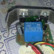
The amplifier is powered by a relay, but it can be excluded from the circuit, since here you can use a direct connection with wires, not so large currents that the wires could not withstand.

The capacitance of the input capacitor can be rejected in one direction or another, this will not affect the operation of the amplifier and the sound parameters in any way, since the amplifier works as a signal repeater. Head load that is connected to an 8 ohm amplifier. It is known that the microcircuit can operate at a load of 2 ohms, with a bridged connection of 4 ohms, to increase the volume, you can use a small transformer (iron) with two windings. The primary must be connected to the output of the amplifier. The primary winding should have a resistance of 3.2-4 ohms, wound with a wire of 0.7-1 mm. We wind the secondary winding with the same wire and it should have the same resistance as the first. Thus, you can increase the power by 1.5-2 times. Author - Artur Kasyan (AKA).
Greetings, dear motorists and radio amateurs! It was sometime in February. My friend, whom I have known most of my life, asked me to assemble the Quack. The main conditions were: low price, power supply from 12 volts, the presence of at least one siren and, in fact, the “crack” function itself.
Having searched a little for the schemes of these "quacks", it turned out that it would be possible to assemble a sensible device only on a microcontroller. I settled on a circuit with a PIC16F628A microcontroller. Up to this point, I was not familiar with microcontrollers, and therefore I had to read a little about them.
After reading a little about them, I realized that I would have to assemble a programmer and I chose the simplest JDM programmer, which consisted of only a few parts, namely a board, four resistors, a 5 volt stabilizer, a COM port connector, a 6F22 battery, and, of course, the very microcontroller.
The programmer is extremely simple and therefore it took me literally 10 minutes to manufacture it (not counting the manufacture of the board).
Programmer circuit:
Finished programmer:
I hid all the “stuffing” of the programmer under electrical tape. This programmer can program MK PIC in DIP8, DIP14, DIP18 packages.
I programmed the microcontroller with the WinPic800 program. If suddenly someone's programmer does not work the first time (like mine), then check if your COM port is enabled in the BIOS settings.
Quack scheme:
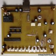
Photo of the finished device:
The diagram contains almost no details. In addition to MK, 33pF capacitors 2 pieces and quartz at 4 MHz are important in it, and the rest is essentially not so important. Sound effects are activated by shorting the corresponding contacts to ground.
The "naked" circuit produces too weak a signal, and therefore it was decided to make an amplifier. We considered such options as TDA2003, TDA2005, TDA7294, TDA7265 and even a transistor amplifier, in the end it was decided to build an amplifier on TDA7265.
The amplifier is switched on by a “bridge” and, according to the developers of the microcircuit, it produces as much as 50 watts of power. The amplifier circuit was taken from the datasheet, I changed it quite a bit, I replaced the 1uF electrolytes with a film. And here is the diagram itself:
The amplifier turned out to be not bad enough, especially since I didn’t chase Hi-Fi, since it’s not needed here. According to measurements, the peak output power was about 40 watts.
I had a board from some PC speakers lying around and it just fit this microcircuit, so having broken the necessary piece, I put the microcircuit and all of its few body kit there. The microcircuit does not require a small heatsink.
Photo of the finished amplifier:
After assembling the amplifier, I thought about how to power the whole thing from 12 volts? The cracker is fine, it requires only 5 volts, but the amplifier needs a bipolar supply +/- 20 volts. It was decided to make a converter on the well-known TL494 chip. It was done according to this scheme:
But I changed the circuit a little, namely, I lowered the power supply capacitors from 4 to one 2200uF 25V and instead of 4 field-effect transistors, I put 2.
R13 is desirable to put 2 watts, as it heats up a little. The converter is turned on by applying “+” power to the “REM” contact.
Transformer W-shaped without gap, primary winding 5+5 turns, secondary 7+7 turns and 4 turns to power the MC. Instead of IRF3205, IRFZ44 and the like are quite suitable.
Photo of the finished converter:
The converter turned out to be quite good and its power is enough to power the amplifier. Everything was placed in a metal case and covered with cardboard. The control panel was placed in a plastic case.
Photos of the finished "Quack":


For voicing children's toys, motorcycles and battery-powered cars, I suggest you make a simple circuit of an audio device that imitates the signal of the "Police Siren". The scheme is simple, contains a small number of details and does not require configuration. It is not difficult to assemble it, you can order flashed microcontrollers from the link at the end of the article.
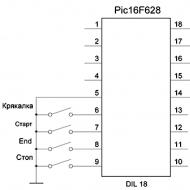
The siren device is assembled on a programmable microcontroller PIC16F628.
The firmware has two different sirens and a Quack.
Schematic diagram of a siren with a power amplifier

Siren circuit board with UM

How to use the siren?
When you press the Quack button, a one-time imitation of the Police Quack is turned on. When you press the "Start" button, "Siren No. 1" is turned on, when you press it again, "Siren No. 2" is turned on. There is also an effect that simulates the end of the sound of the first siren, to enable this effect, click the "End" button. To stop playing the sound effect, click the Stop button. This circuit is easy to assemble and does not require any configuration.
"UM" - Power amplifier, diagram above. This circuit is assembled on a printed circuit board, and there is also a simple stabilizer on the printed circuit board to power the microcontroller.
The buttons for this device were taken from the panel of an old car radio, but simple tact buttons can also be used.
You will also need a PIC programmer. There are many different schemes of programmers on the Internet.
For data transfer, a USB or COM port is usually used.
You can buy a ready-made desired programmer not expensive in China.
Refinement: "Quack with a flasher"
If desired, you can add an LED flasher on the PIC12F675 to the “quack” circuit!

Photo of the assembled board with a flasher


Video of the siren with a flasher
If you want to assemble the proposed siren with a flasher, you can purchase a kit for assembling it with flashed microcircuits at the link: vsmaster.ru

Sergey V. Kamyshin. (For all questions: [email protected])
P O P U L I R N O E:
In cars, two horns are often installed, thus the sound is two-part - both sound at the same time. One high tone signal with a frequency of sound vibrations of about 430 Hz, the other low tone with a frequency of about 320 Hz.
But with the alternating sound of klaxons, the car signal sharply contrasts against the background of similar ones. Previously, we considered a similar scheme:
There is another option...
Related Articles