Do-it-yourself police cracker on PIC. Police cracker (siren) on a PIC microcontroller Schematic diagram of a siren with a power amplifier
Do-it-yourself police cracker on PIC
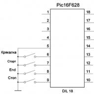
I offer you to repeat the circuit of an audio device that imitates the signal of the "Police Siren". Device done on the microcontroller PIC16F628. The scheme has two different sirens and a Quack.
Basically, a police cracker is put in a car, so see other schemes for cars
You will also need a PIC programmer, here is the schematic

When you press the "Quack" button, a one-time imitation of the "Police Quack" is turned on. When you press the "Start" button, "Siren No. 1" is turned on, when you press it again, "Siren No. 2" is turned on. There is also an effect that simulates the end of the sound of the first siren, to enable this effect, press the "End" button. To stop playing the sound effect, click the "Stop" button. This circuit is easy to assemble and does not require any configuration.

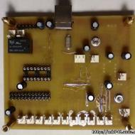
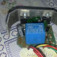
"UM" - Power amplifier, it is not shown in the diagram. This circuit is assembled on a printed circuit board, and there is also a simple stabilizer on the printed circuit board to power the microcontroller.

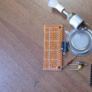
The buttons for this device were taken from the panel of an old car radio, but simple tact buttons can also be used. The housing for the device is made of plastic, size (55X35X15).
I offer you to repeat the circuit of an audio device that imitates the signal of the "Police Siren". The device is made on the PIC16F628 microcontroller. The scheme has two different sirens and a Quack.
When you press the "Quack" button, a one-time imitation of the "Police Quack" is turned on. When you press the "Start" button, "Siren No. 1" is turned on, when you press it again, "Siren No. 2" is turned on. There is also an effect that simulates the end of the sound of the first siren, to enable this effect, press the "End" button. To stop playing the sound effect, click the "Stop" button. This circuit is easy to assemble and does not require any configuration.


"UM" - Power amplifier, it is not shown in the diagram. This circuit is assembled on a printed circuit board, and there is also a simple stabilizer on the printed circuit board to power the microcontroller.

The buttons for this device were taken from the panel of an old car radio, but simple tact buttons can also be used. The housing for the device is made of plastic, size (55X35X15).
You can download printed circuit boards, project in, firmware below
List of radio elements
| Designation | Type | Denomination | Quantity | Note | Shop | My notepad |
|---|---|---|---|---|---|---|
| MK PIC 8-bit | PIC16F628A | 1 | To notepad | |||
| Capacitor | 33 pF | 2 | To notepad | |||
| Quartz resonator | 4 MHz | 1 | To notepad | |||
| Button | Without fixation | 4 | To notepad | |||
| Add all | ||||||
Before starting the article, I want to warn that the use of such signaling devices is illegal, at best, you face a tidy fine. VIP signals have always been considered a luxury item and there are many motorists who would like to have such a device in their car. This is a device that generates powerful low frequency audio signals.
The signal consists of three main parts.
1) Control panel - in new models, very often the entire generator circuit is located in the control panel. Such models as the right have only one MK, which is programmed and has several modes of operation.
2) Power amplifier - Amplifies the signal and feeds it to the emitter
3) Emitter - a loudspeaker that is designed to reproduce a signal.
The generator generates sawtooth pulses and feeds it to the preamplifier, then the signal from the preamplifier goes to the main power amplifier, in our case this amplifier is made on a cheap monophonic TDA2003 chip.
The circuit has a matching transformer, the signal from the UMZCH goes to the primary winding of this transformer. The secondary windings of the transformer are connected to the bases of powerful key transistors. The signal causes the transistors to open, the latter apply voltage to the primary winding of a more powerful (power) transformer.
At the output of this transformer, we already receive an amplified square-wave signal that is fed to the loudspeaker.
The generator (imitation of a cracker) is built on a two-channel pulse generator and divider counters. To simulate the sound of a siren, the circuit has a separate microcircuit.
The design scheme is available in the full archive, the download link of which you can find at the end of the article (free download).
The VIP signal is a special purpose signaling device that is used by intelligence agencies and is not available to civilians, but this is only at first glance. Recently, they brought the very same COP cracker for repairs.
The signal is quite old, although it was used until recently - of course, by civilians. Modern special signals are made on specialized microcontrollers, this can drastically reduce the size of the generator board and the circuit itself as a whole, but this signal was used back in the dashing nineties, so a huge number of components were used to obtain the crackle effect - counters, square-wave generators, a low-frequency amplifier , a matching transformer, an amplifying stage on powerful bipolar switches and a power transformer.
The circuit has three main modes of operation - a loudspeaker, a quack signal and the howl of police sirens. The effect is obtained using a square-wave generator and a counter, then the signal is pre-amplified and fed to the input of a low-frequency amplifier.


The amplifier itself is made on the widely used single-channel TDA2003 microcircuit, which allows you to amplify the input signal rating hundreds of times (the microcircuit provides 10-12 watts of power). Then the signal goes to the primary winding of the matching transformer. That transformer has two secondary windings, each feeding the base of powerful power switches.


Power switches operate according to the amplitude of the base signal, forming a multiple voltage amplification. Amplification is provided by a power transformer. In the circuit, the frequency is regulated within 200 Hertz, therefore all transformers used have an iron core.

For those who like to tickle their nerves, we give you a diagram of a police "quack". We note right away that this case is administratively punishable, so we do not recommend using the device in the city. They will catch you, and they will surely punish you.
For manufacturing, we need to make not only the pulse generator itself, as it might seem at first glance, the legs and the amplifier for it. To begin with, consider the device of the pulse generator.
The frequency of the output pulses should be in the range from 10 to 40 Hz, then you can play with the frequency, it is regulated by one tuning resistor, set to your liking. The NE555 microcircuit is taken as a basis, a low-frequency generator is assembled with attached elements, as shown in the diagram. With a 47 kΩ trimmer, we adjust the frequency of the output signals.

However, the NE555 chip has little power and if the circuit is used directly on the speaker, the signal will be too quiet and will not produce the desired effect. Therefore, the signal from the output of the generator must be amplified. We will assemble the amplifier on a TDA2005 chip, you can also use a less powerful TDA2003 chip, but the effect will not be the same, TDA2003 will provide the amplifier power up to a maximum of 10 watts.

TDA2005, when connected with a bridge, for one speaker (stereo is clear to us, there is nothing here) will provide 20-25 watts of amplification, which is already much more significant. The amplifier circuit is presented below, as well as assembly photos, you can assemble on any circuit board, which are full in any radio store. After assembling the amplifier, we feed the output signal from the generator to the input of the amplifier. The TDA2005 chip (or any other one that you used) must be installed on the heat sink, it will heat up decently, so it is necessary to provide sufficient cooling.

Almost ready, it remains only to connect the speaker. Speakers from old alarm systems are perfect for these purposes. Believe me, the effect will be stunning, so it is advisable to carry out all manipulations for setting up, checking and installing away from the city and large crowds of people. You can also connect a microphone to the input of the amplifier, adding the effect of colloquial speech, in addition to a special signal, to discourage any road user.

If desired, you can build a more powerful amplifier on another TDA7294 chip, but it requires a higher power supply than the car's on-board network. In this regard, it will be necessary to supplement the circuit with a voltage converter. This is a more complex design, but the power of the amplifier can be raised up to 100 watts!


And in the end, we warn you once again that a special signal is prohibited on an ordinary car, if it does not belong to any public services (police, firemen, ambulance, etc.), the use of a special signal for other purposes is punishable by a large fine and confiscation of equipment, believe you these no trouble.
Related Articles