Power off wifi. Device, principle of operation and connection of the Wi-Fi switch
Hello, dear readers and guests of the Electrician's Notes website.
In my past publications, I introduced you to and touch, controlled both manually and from the control panel.
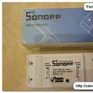
But today I would like to draw your attention to the relay (switch) Sonoff of the Basic version with the ability to control directly from a mobile phone via a Wi-Fi network or the Internet.
The Sonoff Basic relay is a small device (88x38x23 mm) that can be placed behind the ceiling space, in a building niche, or in the bowl of a chandelier or lamp without any problems.

Its cost at the time of publication of the article is a little less than 300 rubles. As you understand, this is quite acceptable money, moreover, for such a modern device. I bought it on the well-known trading platform Aliexpress (the link will be at the end of the article).

The kit included two protective covers with mounting screws, but, unfortunately, there were no instructions.
The Sonoff relay has the following technical specifications, some of which are displayed directly on its body:
- maximum controlled load current 10 (A)
- supply voltage from 90 (V) to 250 (V)
- wireless standard 802.11 b/g/n
- security protocol WPA-PSK/WPA2-PSK
- operating temperature from 0°С to 40°С
- weight about 50 g

Sonoff Basic Relay Capabilities:
- load management via Wi-Fi
- Internet load management
- load control according to a given timer, both with direct and reverse countdown
- load management from multiple mobile phones

These are the possibilities the Sonoff relay has. It can be safely used in smart home systems and for various other needs and requirements.

First, I will tell you how to connect Sonoff, and then we will check all its declared control methods in practice.
So let's go.
Installation and connection of the Sonoff relay
For the Sonoff relay to work, it needs a supply voltage of 220 (V), which means that it can be installed without problems in a place convenient for you, for example, in a chandelier bowl or right under a stretch ceiling, as well as directly in a junction box if there is enough space.


The relay has two mounting holes to mount the relay to a surface.

The Sonoff relay wiring diagram is very simple.
On the terminals (L) and (N) from the side (Input-Input), the phase and zero of the supply voltage 220 (V) are connected, respectively. Naturally, when connecting, do not forget about.


Please note that the wires to be connected must have a cross section of no more than 1.5 sq. mm. But I still tried to connect wires with a cross section of 2.5 sq. mm. As a result, a rigid (single-wire) wire can still be connected without problems, but a flexible (stranded) wire is already inserted into the terminal with great difficulty, so it had to be flattened and deformed a little.

For example, I used a power cable of the PVS brand, which just the same has a cross section of 2.5 sq. mm. At the other end of the cable there is a plug, which I will later plug into any outlet with a voltage of 220 (V).

On the terminals (L) and (N) from the side (Output-Output), the phase and zero load are connected, respectively.

For the convenience of connecting the load, I connected a socket to the relay output.

By the way, terminal covers not only have a protective function, but also play the role of clamps for power wires or cables.


This is how it all turns out nice and neat. Sonoff relay connected.

As a load, I connected an LED lamp, about in one of my articles.

Here is a simple example of a Sonoff relay wiring diagram for a group of luminaires.

By the way, it is not necessary to use only a lamp or a group of lamps as a load. Any other load that does not exceed the rated current 10 (A) can be safely connected to the output terminals. And if you still need to control a load that has a current value above 10 (A), then it can be connected to a contactor, and with the help of a relay you can already control the coil of this contactor.

In this regard, we can add that when using a contactor, you can control at least a single-phase load, at least a three-phase one, at least with alternating current, even with direct current.
It will look something like this.

Thus, the scope of the Sonoff relay is very wide and varied. It can be controlled by at least one light bulb, even a powerful single-phase electric heater, even a three-phase electric motor, etc. It all depends on your needs and requirements.
And now let's look at all the possibilities of controlling the Sonoff relay in more detail.
I will not open the relay and look at its device, there is already enough information on the Internet on this subject - look at the relevant electronics resources. And judging by the reviews, the performance of the relay is quite decent. By the way, who is interested to know, the relay is assembled on the basis of the well-known Chinese microcontroller ESP8266.
Load management via phone via Wi-Fi network
Before I talk about controlling the relay via Wi-Fi, I will say that it can also be controlled manually. To do this, on its body there is a small recessed black button. So, with one short press of it, the relay turns on, and when it is pressed again, accordingly, it turns off. Moreover, for this it is not necessary that the relay be connected to a Wi-Fi network - it will also be controlled in Offline mode.


But in addition to this, the button also carries other functionality, which I will discuss below.
To implement the ability to control the load via Wi-Fi and the Internet, you need to install the eWeLink mobile application on your phone. This app is available for both Android and iOS devices. To facilitate the search for the application, you can use the necessary QR codes on the package.

For Android devices, the eWeLink app can be downloaded for free from Google Play and installed on your phone without any problems. The program interface supports Russian.

For iOS devices, this app is available in the App Store. I have not tried to download and install this application on an iPhone or iPad, so if you have tried this application on iOS devices, please write in the comments about the results.

After installing the eWeLink application, you will need to immediately register, indicating the country and your email address. In this case, the phone must be connected to the Internet.

After that, a verification code will be sent to the mail (valid for 30 minutes), which must be entered in the corresponding line "Email code". On the same page, you must enter a password to enter your future account (at least 8 characters).

By the way, letters reach the mail services Mail.ru and Mail.yandex.ru (Yandex-mail) without problems. But as far as I know, letters with a verification code do not always reach the Gmail.ru (Google mail) mail service, so keep this in mind.
Then it is necessary to pair the relay and the router by holding the same button on the switch body for a long time (for 5 seconds), after which the green LED on the relay will blink. Put a tick on the first connection mode and click "Next".

Now you need to select our Wi-Fi network from the list and enter a password from it. In order not to enter a password each time, you can check the "Remember password" box. Click "Next", after which the search for our device and its registration will begin (in time it took me no more than 2-3 minutes).

After successful pairing, the relay automatically transfers data to the Chinese cloud (Amazon AWS or Coolkit), which makes it possible to control it via the Internet. But I will return to this a little later.
As you can see, our relay is now displayed in the list of all devices (so far it is the only one in the list, but others will appear very soon).

When the relay is online (on the network), the green LED on its body is always on. As soon as the LED starts to blink, it means that the connection with the router or the Internet is lost. Just by this indicator, it is convenient to determine whether the relay is in the network (Online) or not (Offline).
While I was testing this device, I did not notice any problems with the loss of the network. The device is always online and responds stably to control commands.

Now you can try to turn on the relay through the phone. To do this, click on "Relay 1". Immediately, a red inscription appeared stating that the eWeLink application needs to be updated, although the update is not displayed on Google Play.

We go into the device settings (three dots in the right corner) and see that the application has the current version 1.5.2, and a newer version 1.5.5 is available. Click on the "Download" icon and the application update begins. After the update, the red inscription disappears, and in the settings we can see the new current version 1.5.5.

Remember!!! The main condition for the operation of the relay is the availability of Internet access.
If Internet access suddenly disappears, then the green LED on the relay case will flash, and the application will display the Offline mode on its tab, i.e. not available for management.
So, to turn on our "Relay 1", you need to enter it and click on the round virtual button in the center of the screen. Moreover, you can control the relay from the general list of all devices by clicking on the corresponding small button (on the left). In general, whoever likes it.
When the relay is off, the button is white with a gray background around it. When the relay is on, the button changes its color to green, and the background around it turns blue.


In addition to the banal principles of control, you can set the time to turn on or turn off the relay by timer by setting the appropriate date and time for its control.
Moreover, I was surprised that the relay is triggered by a given timer even when it is offline (Offline), which means that all the specified timer programs are stored directly in the relay's memory.

Click on the "Add timer" button and go to the timer settings page. Each timer is configurable to either turn the relay on or off. There are two options for setting the timer:
- single (single operation on a given date and time)
- repeated (periodic triggering on a given date and time, including specifying specific days of the week)

In addition to the countdown timer, there is a countdown timer. Very necessary functionality for certain purposes. It is configured similarly to a direct timer, only with the possibility of a single operation.

In addition to the forward and reverse timers, there is a cyclic timer in the "Settings" tab (three dots in the right corner).

In this tab, you can configure various options for relay operation cycles. I will not talk about this in detail, because. everything here is simple and intuitive.
The total number of configured timers, including the cyclic timer, can be no more than 8. And be careful, because. if different timers are superimposed on each other, none of them may work!!!
Also in the settings you can specify in which position the relay will remain if the 220 (V) power is suddenly turned off from it. There are three options here. By setting the appropriate checkboxes, you can choose that when the 220 (V) power reappears, the relay can either turn on, or turn off, or remain in its original state.
By the way, this is a very handy feature. Just remember the nuance, which, when the 220 (V) power disappears and reappears, for some reason always turns on, and even when it is in the off state. And imagine that you are not at home, the voltage in the network “blinked” a little and the controller turned on the chandelier on its own. Here such an incident will not occur, because. in this case, everything can be customized to your needs.

In addition to the above, all your connected devices in the eWeLink application can be grouped together and combined in various scenarios.

Is it possible to control the relay from several phones at once?
Can! Naturally, at the same time, the eWeLink application must be installed on each phone.
There are two options here. The first option is to log into the eWeLink application with the same name and password from different phones and control the relay.

True, if you enter the application on one phone, and then at the same time enter the application under the same login and password, but on another phone, then an error will occur on the first phone and the application will automatically exit. At the same time, the second phone remains in the application and can be used to control devices.


At the same time, I would like to note that when the relay is controlled from one phone, its status is displayed almost instantly on all phones that are connected to it.
Internet load management
In addition to controlling the relay via a phone via a Wi-Fi network, it can also be controlled via the Internet from anywhere in your location, i.e. absolutely from anywhere in the world where there is Internet access.
So, to control the switch via the Internet, you must log in to the same eWeLink application using your username and password that you specified during registration. And then everything by analogy. The same application, the same settings, the same control buttons, etc., the only difference is that you are not at home within the coverage area of your Wi-Fi network, but at a distance of hundreds and thousands of kilometers from home.
A little about the cloud.
But still, you will not be able to control the relay without the Internet, because. control is not through a local network, but through the Internet, i.e. the same Chinese cloud that I mentioned above. And it doesn’t matter if the control is via Wi-Fi or via the Internet, the control always goes through the cloud, and access to the cloud requires Internet access.
In this regard, various craftsmen have already figured out how to untie this device from the Chinese cloud or make it control only through the local home network. For those who are interested, this information can be found on certain resources.
By the way, if you need a similar device, but with an additional radio control function from the remote control, then you can order the Sonoff RF version relay.

If you want to control the load where there is no Internet at all, then you can use the Sonoff version G1 relay (GSM / GPRS with SIM card support). Also, this manufacturer has available relays with temperature and humidity sensors Sonoff ТН10/ТН16 and two-channel (for controlling two independent loads) Sonoff Dual relays.

In general, the manufacturer Sonoff has many different devices, I will tell you about some of the most interesting and significant ones on the pages of my website, so subscribe to the newsletter so as not to miss interesting releases.
You can buy the Sonoff relay here:
- Sonoff Basic: https://goo.gl/jXyNm3
- Sonoff RF (with radio control): https://goo.gl/TRPqN6
- Sonoff G1(GSM/GPRS with SIM support): https://goo.gl/EkpTdp
- Sonoff ТН10/ТН16 (temperature and humidity sensor): https://goo.gl/MWAL5p
- Sonoff Dual (dual channel): https://goo.gl/a7rV56
And already by tradition, a video based on the materials of the article, where you can more clearly see the configuration and control of the Sonoff relay:
This article will focus on ESP8266 Wi-Fi module, programming language LUA and firmware nodeMCU. The manufacturer's SDK will not be considered.
About three years ago, I tried to implement a switch on a 1-wire bus. I didn't like how it all worked.
- Single point of failure all logic on the server;
- Slow speed;
- To each switch you will have to pull from 2 wires (ideally a “vitukha”).
As a result, all this was successfully abandoned, other wireless solutions were considered, but were excluded due to high cost, insecure protocol and implementation complexity. I wanted something simple with a minimum of components, with its own logic and cheap. Recently ordered 2 pieces. esp8266 just for fun, not knowing exactly what to do with them. After 2 evenings of showdowns with the chip, I remembered the unfinished business with the button and decided to bring it to its logical end.
There are already a number of firmware for this module, you can also write firmware for yourself using the SDK, but I didn’t go into the details of writing, because after studying the nodeMCU API, I realized that this functionality was enough for me with a margin and I flashed both modules.
Iron
Cost is an important factor for a simple switch, so I tried to use as few parts as possible. I decided to make from what was at home, but I had to buy a solid state relay. By the way, the “relay” is more expensive than the wifi module and can be replaced with an optocoupler, a triac and a strapping, switching circuits are easily searched on the Internet. There was a case when a bad contact in the bulb holder knocked out the triac for a short time. Let's see how the opto-relay will show itself, because I have not worked with them before. It is worth considering for a large load the installation of a radiator is required.
Here I immediately ran into a problem, if on gpio, when turned on, it went to the ground, the board switched either to the firmware mode or to an incomprehensible mode, because the button is normally open, there was nothing to redo with it and left it to be closed to the ground, and the opto-relay hung on a plus through a resistor and turned on with a supply of 0, turned off with a supply of 1, respectively. As a result, the following scheme turned out:

Attention, the scheme should be improved! The output to the relay should be fed through the transistor, and the button should be pulled up through the resistor from the plus. The ingredients turned out like this:
- switch;
- spring (for converting the switch into a button);
- esp8266 itself;
- solid state relay used(S202T02);
- scarf for design;
- 470 ohm resistor;
- wires;
- connectors to taste;
- phone charging 400mA 5v;
- stabilizer 1117 3.3v;
- pair of capacitors.
The alteration of the switch did not take much time, I threw out the standard LED. He extended the wires from the module in the center of the switch, placed the module outside under the plastic button, and the power unit inside. Not many photos of the process (photo from the phone):
nodeMCU
The firmware uses the Lua programming language, this language is similar to Javascript. The version is still damp, but already the basic functionality is not badly implemented. Immediately after loading, the module starts executing the script file init.lua, this file is not in the clean firmware, you have to create it manually. All operations can be performed through the console connected to the "com" port, to simplify uploading files to the module, there is a luatool script. The fill works as follows and this code shows the process of writing to a file in full.
File.open("init.lua","w") file.writeline([]) file.writeline([[--comment]]) file.close()
An example of reading a configuration file. It doesn't look very good. Can eat also other variant of the serialized data.
File.open("config") c_wifi_ssid = string.gsub(file.readline(), "n", "") c_wifi_key = file.readline() file.close()
An example loop using the 1000 millisecond pause API is shown below:
Tmr.alarm(1000, 1, function() if wifi.sta.getip()=="0.0.0.0" then --current ip print("connecting to AP..."..c_wifi_ssid.."/". .c_wifi_key) else print("ip: ",wifi.sta.getip()) tmr.stop() -- alarm stop end end)
Working with GPIOs
If you have a module model ESP-01 new revision, you only have 2 gpios available without resorting to a dirty hack.

I decided to abandon such a hack and use what is.
One gpio button and second output to solid state relay. There is also Tx, but I couldn’t get it to work as gpio, and for indication I just pass messages to the console print(). While kostylil just like that. The longer the message, the longer and brighter the LED flashes. The owners of this modification fly through the forest and with such functions as (node.key, node.led), because they can only use GPIO16, which is also not wired on the board.
All gpios can work in several modes (OUTPUT, INPUT, INT), but what is interesting is that the function gpio.read(), before counting, goes low even if OUTPUT mode is set. That is, to get the current state of the exit, this is not suitable. I had to use an external variable and write two functions for convenience, and then define activity through the variable.
Function on() gpio.write(8,gpio.LOW) oo=1 end function off() gpio.write(8,gpio.HIGH) oo=0 end
Events can be used callback gpio.trig(pin, type, function(level)), the second parameter can take the following values "up", "down", "both", "low", "high". Everything seems to be clear here. If your output is in state 1 and we lower it to the ground, it fires down, then it fires up when raised, but, to my regret, this did not happen, in the console I saw only down, depending on the speed of pressing the button, the event fired 1 or 2 times. I decided to put a cycle with a pause and break 1 on gpio.
For i=1,1000 do print(i) tmr.delay(10) tmr.wdclr() -- reset counter and prevent auto-reload end
But the pause did not work, and without a pause, the device went into reboot. But print(i) introduced a good delay. Made through tmr.alarm, but at the current moment there can be only one active cycle, which is not very suitable.
Function down() tmr.alarm(100, 1, function() timer = timer + 1 -- ok if gpio.read(9) == 1 then print(timer) tmr.stop() if timer< 20 then switch() else -- ... end timer = 0 end tmr.wdclr() end) end gpio.trig(9, "down", function (gp) if timer == 0 then timer = 1 down() end end)
HTTP server
The server starts up like 2 fingers, but you won't get any array of request parameters. It is not yet clear which is more optimal: either write your own bicycle, or find by substring. Agree, it looks terrible. In this example, 2 parameters are searched key and mode=off,on,party. The last mode is a simple flashing of a light bulb every 200ms, you can set it faster, but I was afraid for the light bulb and repulsed it.
Function HTTPd() print("start http serv") srv=net.createServer(net.TCP, 5) srv:listen(80,function(conn) conn:on("receive",function(conn,payload) print( payload) if string.find(payload, "key="..c_api_key) then msg = "key_ok" if string.find(payload,"mode=on") then on() else if string.find(payload,"mode =off") then tmr.stop() off() else if string.find(payload, "mode=party") then party(200) end end end else msg = "error_key" end conn:send("
mode=key="api_key"
") end) conn:on("sent",function(conn) conn:close() end) end) endIt is not so difficult to write a simple web interface, and place scripts and styles on external servers. From the module, take only the index page and communicate with it, for example, via json, so there will not be a big load and everything will fit into the file system, but we become dependent on the presence of the Internet.
Good day, dear reader.
Some lyrics at the beginning. The idea of a “smart” light switch is not at all new and, probably, this is the first thing that comes to mind for those who have begun to get acquainted with the Arduino platform and IoT elements. And I am no exception to this. Having experimented with circuit elements, motors and LEDs, I want to make something more applied, which is in demand in everyday life and, most importantly, will be convenient to use, and will not remain a victim of the experiment to the detriment of comfort.
In this article, I'll show you how I made a switch that will work like a normal one (i.e. one that is usually mounted on a wall) and at the same time allow you to control it via WiFi (or via the Internet, as is done in this case).
So, let's make a list of what you need to implement your plan. I must say right away that I intended not to spend a lot on components and chose components based on feedback on the forums and the price-to-quality ratio. Therefore, some components may seem out of place here for experienced electricians, but please do not judge strictly, because. I'm just new to electromechanics and would really appreciate comments from more experienced folks.
I also needed: a server with which the switch will be controlled via the Internet, an Arduino Uno with which I programmed the ESP, a router and consumables like wires, terminals, etc., all this can vary from taste and will not affect to the end result.
Prices are taken from Ebay, where I bought them.
And here is what the elements from the table look like:

Now you can draw up a connection diagram:

As you probably noticed, the scheme is very simple. Everything is assembled easily, quickly and without soldering. A kind of working prototype, with which you do not need to mess around for a long time. Everything is connected by wires and terminals. The only negative is that the relay did not fit into the switch socket. Yes, originally I planned to shove all this into the wall behind the switch to look aesthetically pleasing. But to my regret, there was not enough space in the nest and the relay simply simply did not fit either along or across:

Therefore, I temporarily moved the relay out of the socket until I found a suitable switch box with a socket to hide the iron inside. But there is nothing more permanent than temporary, right? So it all looks like this now:

Electrical tape will save you from electric shock ... I hope.
Now let's talk about the software part.
And before proceeding to the analysis of the code and details, I will give a general scheme for implementing the control of the light bulb.

I hope someday I will rewrite everything and the communication will be based on a faster protocol than HTTP, but for a start it will do. Remotely, the light bulb changes its state in about 1-1.5 seconds, and from the switch instantly, as befits a decent switch.
Programming ESP8266-01
The easiest way to do this is with an Arduino. You can download the necessary libraries for the Arduino IDE from GitHub. All installation and setup instructions are there.Next, we need to connect the ESP to the computer, for this you need either a USB to Serial Adapter (such as FTDI , CH340 , FT232RL) or any Arduino platform (I had an Arduino Uno) with RX and TX outputs.
It is worth noting that the ESP8266-01 is powered by 3.3 Volts, which means that in no case should you connect it to the Arduino power supply, which are (often) powered by 5 Volts, otherwise everything will burn to hell. You can use a voltage reducer, which is shown in the table above.
The connection scheme is simple: we connect TX, RX and GND ESP to RX, TX and GND of the adapter / Arduino, respectively. After that, in fact, the connection is ready for use. The microcontroller can be programmed using the Arduino IDE.
A couple of nuances when using the Arduino Uno:
- The Uno has a 3.3V output, but it was not enough. When ESP is connected to it, everything seems to work, the indicators are on, but the connection with the COM port is lost. So I used a different 3.3V power supply for the ESP.
- In addition, UNO did not have any problems communicating with ESP, given that UNO was powered by 5V, and ESP by 3V.
And here is the program for ESP itself:
Show Code
#include
A couple of notes on the code:
- It is very important to declare the GPIO0 pin as pinMode(button, INPUT_PULLUP), because in the circuit, we do not use a resistor for this button. And ESP has its own "wired" for these very purposes.
- When catching the state of the button, it is desirable to set a delay when reading in order to avoid false positives at the moment of pressing.
Web server programming
Here you can give free rein to your imagination and use any available means to create a service that will process requests sent by the switch and send requests to turn it on / off.I used for this purpose
In the modern world, the “smart home” system is becoming common. With its help, you can remotely control many elements and devices of our home. You can also remotely control the lighting in the room. Such inventions contribute to the comfort of this room, and are also used where the elderly and people with disabilities live. This article will discuss how it works and why you need a Wi-Fi light switch, which is gaining more and more popularity among the population.
Strengths and weaknesses of the device
Wi-fi light switch has the following advantages:
- No need to lay additional cable.
- It is possible to centrally control lighting devices, that is, from one command point. In order to control the wireless light switch, you can use a smartphone, tablet, computer, as well as a remote control. For tablets and other electronic devices, the necessary software must be installed. It can be downloaded from the Internet or installed from a disk.
- Large signal coverage area. Despite the walls, the digital radio signal penetrates into the right room.
- This system is very secure. Even if the design of the device is damaged, it does not threaten the tenant with a strong electric shock, because the Wi-fi switch has a very small current strength.
- The device normally works with all types of light bulbs (LED, incandescent, energy-saving).
- You can set different combinations, as well as modes of operation of lighting devices.
If we talk about the shortcomings of light switches, then there are only a few of them. The main ones are that the price is much higher than conventional keyboard models and there is a certain risk of running out of batteries in the remote control, or a bad Wi-fi signal.
Design features
The set of Wi-fi switches includes a receiver and a transmitter. The receiver is a relay on the control. It can be controlled via a smartphone with access to a Wi-fi network, or using a remote control. When the relay receives a certain signal, it closes the wiring circuit. The relay is installed near or inside the luminaire. This is possible due to the small dimensions of the device. The reason for installing the instrument near a light fixture is so that it does not fall out of the radius in which the transmitter is operating. If there is spot lighting in the room, then the receiver can be placed in a junction box or behind a false ceiling.

The switch or transmitter has a small power generator that is capable of generating electricity when a remote control button is pressed or a specific command is sent from a smartphone via a Wi-fi connection. In turn, the pulse is processed into a radio signal that enters the device. Such radio-controlled light switches are quite expensive, and their analogue is regulation from a remote control in which batteries are located.
Types of switches and the best manufacturers
At this time, the range of Wi-fi light switches is not too large. However, products are classified according to several criteria:
- The device can be controlled by electronic or mechanical keys. In the first case, we are talking about the touch screen of the device. The keys are located on the remote control (remote control).
- There are also light switches with both and regular keyboards. With the help of the first devices, it is possible to adjust the brightness of the lighting, thereby changing its intensity. To adjust the brightness, either hold or scroll the corresponding button.
- This switch can provide full control of not only one, but also two or three groups of lighting devices. However, the price of a wireless device that can control entire groups is quite high.

At the moment, there are seven main manufacturers of wireless electrical fittings for lighting control:
- Legrand - the country of manufacture is France. The company has a whole line of products called Celian.
- Vitrum is a country of origin Italy. This company uses a technology called Z-Wave. It allows you to fully automate the control of lighting in the house.
- Delumo - products are manufactured by a Russian company that, in particular, produces dimmers, switches and thermostats.
- Noolite - accessories are made by Belarusian manufacturers.
- Livolo is a manufacturer in China. This company produces specialized devices for automation. Also in the product line there are products for both single and double frames for switches.
- Broadlink (China). This manufacturer has a fairly large selection of products for lighting control.
- Kopou is the latest company to also be based in China. The manufacturer manufactures dimmers in the form of various key fobs.
The video below provides an overview of another interesting Wi-fi light switch model:
Correct connection
In order to properly mount the switch, you need to know its principle of operation, what the device consists of and how to connect the Wi-fi switch. The wiring diagram for this wireless device is very simple.

One of the benefits of a Wi-Fi light switch is that it is easy to use and connect. With a strong desire, you can install the device with your own hands. It is important that you follow the manufacturer's instructions exactly. This installation only takes a few minutes.
The connection process consists of only two steps:
- Installing a radio receiver.
- Installation of a light switch (control buttons).
Most receivers have two to four wires. They come out of the body of the device. To determine the input wire, you must read the instructions. The remaining wires will be output, for example, a double switch will have two outputs. To install the receiver, open the phase that supplies power to the lighting fixture and connect it to the circuit, while following the sequence.

If more than one lighting group needs to be connected, proceed as follows:
- zero is applied to all lighting fixtures;
- phase forks in Wi-fi switch;
- phase should be applied separately to each group of luminaires.
The control button is installed quite simply, first you need to make a hole in the wall using a perforator with a concrete cutter. An ordinary plastic socket is inserted into the finished hole, and gypsum can be used to fix it. The installation process is absolutely no different from the keyboard type. The only difference is that there is no need to lay wires, you just need to securely fasten the button in the socket.
Like( 0 ) I do not like( 0 )
From the article you will learn why you need a wireless switch, scope and varieties, device and principle of operation, advantages and disadvantages, selection criteria, how to connect with your own hands, circuits.
Wireless network switches fundamentally change the idea of controlling lighting devices, simplify our life and make it more comfortable.
Until recently, such technologies were not available due to the high price and limited production.
At the present stage, there is a tendency to reduce their cost. That is why radio switches and their other analogues are increasingly perceived as an alternative to classic switches.
What is a wireless switch for?
Remote systems that provide remote control of certain devices are becoming more common. The wireless wall switch is no exception.
It was created to increase comfort, and for the elderly and people with disabilities, it is completely necessary.
With the help of such a device, you can easily control the lighting in the house, change the brightness, turn the lamps on and off.
In addition, due to the special design, there is no need to damage the walls and make large holes for mounting.
Scope of application
Traditional switches are gradually becoming a thing of the past due to the inconvenience of use, the complexity of connection and installation, as well as a small resource. Wireless analogs have the best qualities.
They are stylish and install in minutes.
The use of such products is relevant in the following cases:

Varieties
Wireless switches do not differ in variety, but there is still a certain choice.
They are classified according to three main features:
- By type of management;
- If possible, adjust the level of illumination;
- By the number of lighting devices they control.
Taking into account the classification mentioned above, the following types of wireless switches can be distinguished:

The device and principle of operation of the main elements of the device
The wireless switch consists of the following elements:

Electrical wiring is required only for the lamp and power supply to the receiver of the product. As noted above, the signal is transmitted using an infrared pulse or radio waves.
The second control option is more preferable, because control is possible at a great distance and even from another room.
Installation of the product is carried out according to a simple scheme, for the implementation of which you do not need to have deep knowledge in the field of electrical engineering.
The old switch can be left as an additional on / off source when the battery in the control panel is low.
Light control is done in the following ways:
- By touching a special touch panel;
- By pressing a mechanical button;
- Sending a signal from the remote control or phone.
With remote control from the remote control, the signal is transmitted at radio frequencies, which eliminates the presence of interference and increases the reliability of the device.

Walls, furniture and other elements of the interior will not interfere with the command to turn on or off the light source.
Using the remote control, you can simultaneously control a group of wireless switches (up to 8 pieces). Thanks to this, you can not walk around the apartment or house to turn off the light somewhere in the toilet or bathroom.
The range of the remote control depends on many factors - the model of the product, the design features of the building, the materials used in the manufacture of partitions.

Most often, the signal is transmitted at a distance of twenty to twenty-five meters. The transmitter is powered by batteries.
The disadvantage of the remote control is that it is constantly lost and the lighting has to be controlled manually.
That is why touch-sensitive wireless switches that respond to a normal touch and are used in Smart Home systems are gaining more and more popularity.
Some radio switches can not only turn the lamp on and off, but also adjust the level of illumination. In this case, the scheme is supplemented with one more element - .

The regulation process is carried out using a wireless switch. To change the light level, press and hold your finger on a button or key.
Advantages and disadvantages of wireless switches
Despite the ease of use, wireless load switches (in our case, lighting) have not only advantages, but also disadvantages. But more about everything.
- Ease of installation. For installation and connection, it is not required to gouge the walls and lay a separate "branch" of electrical wiring.
- The ability to control several light sources at once from the remote control or via a smartphone.
- Large range of action. The control signal in an open area can reach the receiver at a distance of up to 30 meters. At the same time, walls or pieces of furniture are not an obstacle.
- Safety for adults and children. Even accidental damage to the structure does not pose health risks. The operating current in wireless remote switches is minimal and not hazardous to health.
- The cost of such products is higher than the classic "wired" switches. Conservatives and conservatives prefer familiar products.
- Inability to control due to low battery in the remote control or inability to control due to poor Wi-Fi connection.
Features and principle of operation of the remote light switch
Let's take a closer look at the wireless control system. It includes a set of equipment that is used to control the level of illumination in an apartment or house.
For control, not a standard switch is used, but a special remote control or telephone (this was partially mentioned above).

The control panel (depending on the model) can be designed for a different number of channels. It can act on one or a whole group of lamps (up to several dozen).
In the most advanced systems, switching on is done using a motion sensor that signals the need to turn on the light if a person approaches the controlled area.
If you set up the motion sensor correctly, it will only respond to a person.
The remote switch is based on a radio transmitter. It is he who transmits the on / off signal to the lighting devices.
The range, as noted above, in most devices is up to 30 meters. But on sale you can find models that can transmit a signal at a distance of up to 300 meters.
The radio transmitter receives a signal from the remote control, and then transmits it to the light sources. The remote control, as a rule, has two channels, but there are also eight-channel models.
The control can also be carried out using a switch in which the transmitter is built.

Radar is often included with a wireless remote device. It is used to connect the remote control and sockets. It can be controlled via mobile phone. Such devices are called GSM-switches.
Management can be done in one of the following ways:

Features to look out for when choosing
When buying a wireless remote switch, you should pay attention to the following parameters:
- The type of light bulbs that the device controls;
- Material, color and appearance of the case;
- Working voltage;
- Number of channels;
- Radius of action;
- Dimensions;
- Rated current;
- Equipment.
You should also pay attention to the following criteria:
- Operating frequency range;
- signal transmission method;
- The presence of an encoding;
- Transmitter power type;
- Estimated battery replacement time;
- fastening method;
- Working temperature range;
- Price.
What does the market offer?
A wide range of wireless remote switches allows you to choose a product based on price, features and appearance.
Below we consider only a few models that the market offers:
- Fenon TM-75 is a remote-controlled switch made of plastic and rated for 220 V. The features of the device include the presence of two channels, a 30-meter range, a remote control and a delayed turn-on function.
 Each channel can be connected to a group of lighting fixtures and controlled. The Fenon TM-75 wireless switch can be used with chandeliers, spotlights, LEDs, and other appliances powered by 220 volts.
- Inted 220V is a wireless radio switch designed for wall mounting. It has one key and is installed in combination with the receiving unit. The operating voltage of the product is 220 Volts, and the range is 10-50 meters. The wireless light switch is mounted using self-tapping screws or double-sided tape. The body is made of plastic.

- INTED-1-CH is a light switch with remote control. With this model, you can control the light sources remotely. The power of the lamps can be up to 900 W, and the operating voltage of the product is 220 V. Using the radio switch, you can control the equipment, turn on and off the light or alarm. The product is based on a receiver and a transmitter. The latter has the form of a key fob, which has a small size and transmits a signal at a distance of up to 100 m. The body of the product is not protected from moisture, so additional protection must be provided for outdoor installation.

- Wireless touch switch controlled via remote control. The product is wall-mounted, small in size and made of tempered glass and PVC. The operating voltage is from 110 to 220V, and the rated power is up to 300W. The package includes a switch, remote control and bolts for attaching the accessory. The average life cycle is 1000 clicks.

- Inted 220V for 2 receivers - wireless light switch for wall mounting. Management is made by means of two keys. The body is made of plastic. The operating voltage is 220 V. The number of independent channels is 2.

- BAS-IP SH-74 is a wireless radio switch with two independent channels. Management is carried out using a mobile phone on the Android operating system. To work, you need to install the BAS application. Model SH-74 is used to control incandescent lamps with a power of up to 500 W, as well as fluorescent light bulbs (power limit - 200 W).

- Feron TM72 is a wireless switch that controls lighting at a distance of up to 30 meters. Light sources are combined into a receiving unit, and switching on and off is done using the remote control. The TM72 model has two channels, each of which can be connected to a specific group of devices. The product has a large power reserve per channel (up to 1 kW), which allows you to connect various types of light source. A big plus of the model is the presence of a delay equal to 10 to 60 seconds.

- The Smartbuy 3-channel 220V wireless switch is designed to connect light sources to three channels with a power limit of up to 280 W. The rated supply voltage is 220 V. The control is carried out from the remote control, which has a range of 30 meters.

- Z-Wave CH-408 is a wall-mounted radio switch that allows you to program various lighting control scenarios. If necessary, up to eight switches can be connected to it. Of the additional features, it is worth highlighting the management of Z-Wave devices (up to 80) and ease of configuration, regardless of the main controller. The device is powered by two batteries, when they are discharged, a corresponding signal is given. The firmware is updated via the Z-Wave network. The maximum distance to the controller should not exceed 75 meters. Protection class - IP-30.

- Feron TM-76 is a wireless light switch that is controlled remotely using a radio signal. The receiver is connected to light sources, and the remote control controls the receiving unit at a distance of up to 30 meters. The Feron TM-76 model has three independent channels, to each of which you can connect your own group of lighting fixtures. Management in this case will be carried out separately, using the remote control. The maximum power reserve is up to 1 kW, which allows you to connect lamps of various types (including incandescent ones). The operating voltage is 220 V.

How to connect a DIY wireless remote switch
Consider the procedure for connecting a wireless switch using the Zamel RZB-04 as an example.
The following items are included with the model:
- 2-channel radio receiver of small dimensions (type ROP-02);
- 2-channel 4-mode radio switch (type RNK-04);
- Fastening for installation of the product (dowels with self-tapping screws, as well as foamed double-sided tape).

The receiver can operate in five different modes:
- Inclusion. When the key is turned on, one or more lamps are ignited. You can set the inclusion to any of the positions of the keys.
- Shutdown. The principle is similar to that discussed above. The difference is that when you press the key, the light turns off.
- Monostable. In this mode, the light will be on only while the button is pressed. When released, the lamp turns off.
- Bistable. In this case, each press leads to a change in state - switching on and off occurs cyclically.
- Temporary. Here, after pressing the key, the light will burn for a certain time. This option is useful when installing a wireless switch in an entryway, bedroom, or long hallway. At the entrance, you can turn on the light, walk a certain distance (walk to the bed), after which the light will turn off.
To properly connect the receiver, carefully study the diagram. First, apply voltage (connect phase and zero). Only a phase wire is laid to the switch, without zero, therefore its installation is carried out at the place where the lamp (chandelier) is installed.

If there is a monolithic ceiling in which it is impossible to install the receiver, hide the product in the socket. In other cases, the controller is installed at the base of the chandelier, which is considered the most convenient option.

To obtain a phase that will go seamlessly and constantly supply voltage to the receiving device, you need to turn on the switch or connect the wires directly.
The second option is preferred. Before performing this work, it is recommended to turn off the electrical power supply using the machine and check the absence of voltage.

Now you need to make an unbreakable phase, for which the phase is connected to one of the wires heading to the chandelier. To ensure maximum reliability, use VAGO terminal blocks.
When performing work, a wiring diagram for the remote switch should be at hand.
It shows how to connect the device:
- To contact "L" it is necessary to bring a phase wire. At the same time, it is not necessary to conduct it through the switch - the product operates in a constant mode.
- Connect the neutral conductor, which is taken from the junction box, to the “N” terminal.
- A phase is connected to the “OUT1” contact, which goes to a group or one lamp. Here you need a 0th conductor, which can be taken from the junction box or receiver (terminal N).
- To "OUT2" connect the phase that goes to the second group or one lamp. As in the previous case, zero is taken from the junction box or from the N terminal block of the receiver.
- Connect an impulse switch to "INT1". The peculiarity is that when pressed, it sends only a short-term signal. After operation, the operating mode of the 1st group of lamps changes. Thanks to this feature, the ROP-02 receiver can be controlled using a remote control or a stationary impulse switch.
- To "INT2" it is required to connect an impulse switch (one or a group). After clicking on it, the mode of operation of the 2nd group will change. The principle here is the same as described above.

Now you need to combine the remote light switch with the receiving device, connect them to each other and decide on the mode of operation. To do this, you first need to supply electricity.
Now select the appropriate switch mode. Most often, the standard option is suitable - when the switch is moved up, it turns on, and down, it turns off.
To program this mode, do the following:

The second button is reprogrammed in a similar way. The difference is that all manipulations will be performed with the second (unprogrammed) key.
Once the work is completed, proceed to mount the product on the wall. To do this, the kit includes adhesive tape with a double-sided sticky base, as well as dowels with self-tapping screws.

The easiest way is to use double-sided tape, because this does not require any tool. In addition, if necessary, you can change the position of the switch.

For ease of use, the double-sided adhesive tape is divided into four small squares, which are glued around the perimeter of the product, you must first remove the protective layer. It remains to put the switch in the chosen place according to the level.

The installation of the wireless remote switch is completed, and you can put a test lamp, and then check the system's performance.
To do this, switch the key up - the light should light up, and down - go out. When the switch is activated, the indicator lights up.
Wireless remote switches until recently belonged to the category of new and inaccessible technologies. With the growth of production and competition, the price decreases, which makes the purchase affordable for everyone.
The main thing is to carefully approach the choice of product, deal with the main parameters and give preference to models from trusted manufacturers.
Related Articles