Homemade for making spikes on wood. We make spikes with a manual milling cutter
For full-fledged work with a manual router, in addition to the tool itself, the material and the corresponding set of cutters, it is necessary to have one more component - fixtures. In order for the cutter to form the workpiece in accordance with the master's intent - cutting the material exactly where it is required - it must be in a strictly defined position relative to the workpiece at any given time. To ensure this, numerous devices for a manual milling cutter serve. Some of them - the most necessary ones - are included in the instrument delivery set. Other milling devices are purchased or made by hand. At the same time, home-made devices are so simple that for their manufacture you can do without drawings, using only their drawings.
Parallel stop
The most used device, which comes with the kit for almost every router, is a parallel stop, which ensures the rectilinear movement of the cutter relative to the base surface. The latter can be a straight edge of a workpiece, a table or a guide rail. The parallel stop can be used both for milling various grooves located on the face of the workpiece, and for processing edges.Parallel stop for a manual router: 1 - stop, 2 - rod, 3 - router base, 4 - rod stop screw, 5 - fine adjustment screw, 6 - movable carriage, 7 - movable carriage stop screw, 8 - pads, 9 - screw stop stop.

To set the device in working position, it is necessary to push the rods 2 into the holes of the frame 3, providing the necessary distance between the support surface of the stop and the axis of the cutter, and fix them with the locking screw 4. For precise positioning of the cutter, you need to release the locking screw 9 and turn the fine adjustment screw 5 set the cutter to the desired position. For some models of the stop, the dimensions of the supporting surface can be changed by shifting or expanding the support pads 8.
If one simple part is added to the parallel stop, then with its help it is possible to mill not only straight, but also curved grooves, for example, to process a round workpiece. Moreover, the inner surface of the bar located between the stop and the workpiece does not have to have a rounded shape, repeating the edge of the workpiece. It can also be given a simpler form (Figure "a"). In this case, the trajectory of the cutter will not change.

Of course, the usual parallel stop, thanks to the recess in the center, will allow you to orient the router along the rounded edge, however, the position of the router may not be stable enough.
The guide bar is similar in function to the rip fence. Like the latter, it provides a strictly rectilinear movement of the router. The main difference between them is that the bar can be set at any angle to the edge of the workpiece or table, thus providing any direction of movement of the router in the horizontal plane. In addition, the tire may have elements that simplify the performance of certain operations, for example, milling holes located at the same distance from each other (with a certain step), etc.
The guide rail is attached to the table or workpiece with clamps or special clamps. The tire can be equipped with an adapter (shoe), which is connected to the base of the router with two rods. Sliding along the profile of the tire, the adapter sets the rectilinear movement of the cutter.
Sometimes (if the distance of the tire from the router is too close), the bearing surfaces of the tire and the router may be in different planes in height. To align them, some routers are equipped with retractable support legs that change the position of the router in height.
Such a device is easy to do with your own hands. The simplest option is a long bar fixed to the workpiece with clamps. The design can be supplemented with side stops.

By placing a bar on two or more aligned blanks at once, they can be grooved in one pass.

When using a bar as a stop, it is inconvenient to place the bar at a certain distance from the line of the future groove. This inconvenience is devoid of the following two devices. The first is made from boards and plywood fastened together. In this case, the distance from the edge of the stop (board) to the edge of the base (plywood) is equal to the distance from the cutter to the edge of the router base. But this condition is met only for a cutter of the same diameter.. Thanks to this, the device quickly aligns with the edge of the future groove.

The following fixture can be used with cutters of different diameters, plus when milling, the router rests with its entire sole, and not half, as in the previous fixture.


The stop is aligned along the edge of the hinged board and the center line of the groove. After fixing the stop, the folding board leans back, making room for the router. The width of the folding board, together with the gap between it and the stop (if any), must be equal to the distance from the center of the cutter to the edge of the router base. If you focus on the edge of the cutter and the edge of the future groove, then the device will work with only one cutter diameter.
When milling grooves across the fibers, at the exit from the workpiece, when milling an open groove, cases of wood scuffing are not uncommon. The following devices will help minimize scuffing, which press the fibers at the exit of the cutter, preventing them from chipping off the workpiece.


Two boards, strictly perpendicular, are connected with screws. Different cutters are used on different sides of the stop so that the width of the groove in the fixture matches the width of the groove of the part to be milled.
The other open slot milling fixture can be pressed tighter against the workpiece to further minimize tearing, but it only fits a single diameter cutter. It consists of two L-shaped parts connected on the workpiece with clamps.


Copy rings and templates
A copy ring is a round plate with a protruding collar that slides along the template and provides the necessary trajectory for the cutter. The copy ring is attached to the sole of the router in various ways: it is screwed into a threaded hole (such rings are in the photo below), the antennae of the ring are inserted into special holes on the sole or screwed.

The diameter of the copy ring should be as close to the diameter of the cutter as possible, but the ring should not touch the cutting parts of the cutter. If the ring diameter is larger than the cutter diameter, then the template must be smaller than the finished parts to compensate for the difference between the cutter diameter and the copy ring diameter.

The template is fixed on the workpiece with double-sided tape, then both parts are pressed with clamps to the workbench. When you have finished milling, check that the ring is pressed against the edge of the template during the entire operation.
You can make a template for processing not the entire edge, but only for rounding the corners. In this case, using the template shown below, it is possible to make roundings of four different radii.


In the figure above, a cutter with a bearing is used, but the template can also be used with a ring, only either the ring must exactly match the diameter of the cutter, or the stops should make it possible to move the template away from the edge by the difference in the radius of the cutter and the ring. This also applies to the simpler version shown below.


Templates are used not only for milling edges, but also for grooves on the plate.

The pattern can be adjustable.


Template milling is a great method for cutting grooves for hinges.


Devices for milling round and elliptical slots
Compasses are intended for the movement of a milling cutter on a circle. The simplest device of this type is a compass, consisting of one rod, one end of which is connected to the base of the router, and the other has a screw with a pin at the end, which is inserted into the hole that serves as the center of the circle along which the cutter moves. The radius of the circle is set by the displacement of the rod relative to the base of the router.
It is better, of course, that the compass was made of two rods.

In general, compasses are a very common device. There are a large number of branded and home-made devices for circumferential milling, differing in size and ease of use. As a rule, compasses have a mechanism that provides a change in the radius of the circle. Usually it is made in the form of a screw with a pin at the end, moving along the groove of the device. The pin is inserted into the center hole of the part.


When it is necessary to mill a circle of small diameter, the pin must be located under the base of the router, and for such cases other devices are used that are attached to the bottom of the base of the router.

Ensuring the movement of the cutter in a circle using a compass is quite simple. However, one often has to face the need to perform elliptical contours - when inserting mirrors or oval-shaped glasses, arranging arched-type windows or doors, etc. Device PE60 WEGOMA (Germany) is designed for milling ellipses and circles.


It is a base in the form of a plate, attached to the surface using vacuum suction cups 1 or screws, if the nature of the surface does not allow fixing with suction cups. Two shoes 2, moving along intersecting guides, ensure the movement of the router along an elliptical path. When milling a circle, only one shoe is used. The fixture kit includes two mounting rods and a bracket 3, with the help of which the router is connected to the plate. The grooves on the bracket allow you to install the router in such a way that its supporting surface and the base of the plate are in the same plane.
As you can see from the photos above, the milling cutter was used instead of a jigsaw or band saw, while, due to the high speed of the cutter, the quality of the machined surface is much higher. Also, in the absence of a manual circular saw, the router can replace it.
Devices for milling grooves on narrow surfaces
Grooves for locks and door hinges, in the absence of a milling cutter, are performed using a chisel and an electric drill. This operation - especially when making a groove for an internal lock - takes a lot of time. Having a milling cutter and a special device, it can be done several times faster. It is convenient to have such a fixture that allows milling slots of a wide range of sizes.To make grooves in the end, you can make a simple fixture in the form of a flat base attached to the sole of the router. Its shape can be not only round (according to the shape of the base of the router), but also rectangular. On both sides of it, you need to fix the guide pins, which will ensure the rectilinear movement of the router. The main condition for their device is that their axes are in line with the center of the cutter. If this condition is provided, the groove will be located exactly in the center of the workpiece, regardless of its thickness. If it is necessary to move the groove to one side or another from the center, a bushing with a certain wall thickness must be put on one of the pins, as a result of which the groove will shift in the direction from which the pin with the bushing is located. When using a router with such a device, it must be driven in such a way that the pins are pressed on both sides to the side surfaces of the part.

If you attach a second parallel stop to the router, you will also get a device for milling grooves in the edge.

But you can do without special devices. For the stability of the milling cutter on a narrow surface, boards are fixed on both sides of the part, the surface of which should form a single plane with the surface to be machined. When milling, the router is positioned using the parallel stop.

You can make an improved version that increases the area of \u200b\u200bsupport for the router.


Device for processing balusters, pillars and other bodies of revolution
The variety of work that is performed by a manual milling cutter sometimes dictates the need for independent manufacture of devices that facilitate the performance of certain operations. Branded devices are not able to cover the entire range of work, and they are quite expensive. Therefore, home-made fixtures for a router are very common among users who are fond of working with wood, and sometimes do-it-yourself fixtures either outperform branded counterparts or have no branded counterparts at all.Sometimes there is a need to mill various grooves in the bodies of revolution. In this case, the device shown below may be useful.


The device is used for milling longitudinal grooves (flutes) on balusters, poles, etc. It consists of a body 2, a movable carriage with a milling cutter 1, a disk for setting the angle of rotation 3. The device works as follows. The baluster is placed in the body and fixed there with screws 4. Turning to the desired angle and fixing the workpiece in a strictly defined position is provided by disk 3 and locking screw 5. After fixing the part, the carriage with the router is set in motion (along the guide rails of the body), and milling a groove along the length of the workpiece. Then the product is unlocked, rotated to the required angle, locked and the next groove is made.
A similar fixture can be used instead of a lathe. The workpiece must be slowly rotated by an assistant or a simple drive, for example, from a drill or a screwdriver, and excess material is removed by a milling cutter moving along the guides.
Stud milling fixtures
Tenon cutters are used for milling the profile of tenon joints. In the manufacture of the latter, greater precision is required, which is almost impossible to provide manually. Tenoning devices allow you to quickly and easily complete the profile of even complex joints such as dovetails.
The figure below shows an industrial sample of a tenoning device for the manufacture of three types of connections - "dovetail" (deaf and through version) and through connection with a straight tenon. Two mating parts are installed in the fixture with a certain shift relative to each other, controlled by pins 1 and 2, then they are processed. The exact path of the cutter is set by the shape of the groove in the template and the copying ring of the router, which slides along the edge of the template, repeating its shape.


When using the content of this site, you need to put active links to this site, visible to users and search robots.
Knowing how to make a tenon groove with a manual router, you can even make at home not only beautiful, but also reliable furniture, but also various wood structures, characterized by excellent bearing capacity. According to the "thorn-groove" system, not only elements of various furniture (tables, chairs and shelves) are connected, but also the frames of low-rise buildings that experience significant loads during operation.
In order to make a spike on a wooden beam with a manual milling cutter, several conditions must be met:
- securely fix the workpiece and correctly orient it in relation to the guide sole of the router;
- set the height of the working part of the cutter so that the tool removes a layer of material of the required thickness from the surface of the workpiece being processed.
Even using the simplest tenoning device for a milling cutter when performing such processing, you can not only increase its productivity and quality of the result, but also make the process safer. It is especially important to use such a device, which can be made with your own hands, in cases where the furniture is produced not in single copies, but in series (in this case, the master has to perform a large number of such operations both with the same type and with wooden furniture of various shapes and sizes). details).

Tools Used
The creation of spikes and grooves, with the help of which the connection of two wooden blanks will be ensured, assumes that a sample of the material is made on the side surface of the beam or board with a manual milling cutter. In this case, all geometric parameters of the elements of the future connection must be strictly observed.
To perform this operation with a hand router, you can use tools with shank diameters of both 8 and 12 mm. The most versatile in this case is the groove cutter, the cutting part of which works as follows:
- the side surface forms the walls of the groove and the sides of the tenon;
- the end side processes the bottom of the groove and removes a layer of material of the required thickness from the base of the spike.

Thus, using a tool of this type, it is possible to form both a tenon and a groove on the side surface of a beam or board. At the same time, their sizes can be adjusted within a fairly wide range.
In cases where higher requirements are placed on the reliability of the connection of wooden parts, the grooves and spikes are made not of a rectangular shape, but of a shape called the “dovetail”. Grooves and spikes of this configuration are created using dovetail cutters. It is also possible to perform the procedure for forming grooves and spikes of this shape with a hand mill, but for these purposes, devices of a different design should be used.

Dovetail sampling using a template
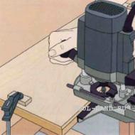
So that the question of how to make a groove in a board and a beam or a spike on their side surface does not cause any particular difficulties, it is better to use a power tool equipped with comfortable side handles, a wide guide sole and the option of protecting the spindle from turning during the replacement of the cutter. In addition, it is desirable that such equipment has a side stop, due to which the overhang of the cutter used with it in the kit will always remain constant.
How to make a stud picker
When forming spikes on wooden blanks with a manual milling cutter, it is not fixed in space in any way and is brought to the workpiece manually. That is why it is very important that when using a power tool, the workpiece is in a fixture that can ensure not only its secure fixation, but also the accuracy of the spikes formed on its surface.
The design of the simplest device that is able to cope with such tasks is:
- several fixed guides (lower, upper, side);
- movable bar, due to which you can adjust the length of the sample.

Such a device is manufactured, the dimensions of the components of which are selected individually, in the following sequence:
- Along the edges of the plywood sheet, side vertical elements of the same height are fixed, in the central part of which cutouts are made.
- Guides are installed on the side elements, along which the sole of the hand mill will move.
- To limit the travel of the hand router along the upper rails, the side rails should be fixed on them.
- On a sheet of plywood, which plays the role of the base of the device, it is necessary to install a movable element, with which the amount of overhang of the edge of the workpiece to be processed will be adjusted. For fixing, you can use a regular thumb screw or any other suitable fastener.
In the manufacture of the device of the proposed design, the following points should be taken into account:
- The height of the top guides should be the sum of the thickness of the workpiece and the amount of small clearance required to install the fixing wedge.
- The cutouts in the side vertical elements are made so wide that it takes into account the length of the spike being formed.

It is possible to work with the device of the proposed design with a manual milling cutter of almost any modern model, the options of which provide for the possibility of adjusting the cutting speed, the amount of feed and overhang of the working part of the tool used.
To create a dovetail spike on the side surface of a beam or board, a device manufactured as follows is used.
- A hole is made in a sheet of plywood, from which the cutting part of the dovetail cutter will protrude.
- A manual router is fixed from the bottom of the prepared plywood sheet. To do this, you can use clamps, screws or any other fasteners.
- On the surface of the plywood sheet, along which the workpiece will move, a board 2.5 cm thick is fixed. It will act as a guide element. Such a board is a consumable and is used once with a cutter of a certain diameter.

Such a device can be installed between two chairs or used to place it in a more convenient and reliable design.
Creating spikes on bars and boards
Using wood splicing cutters for a hand router and the above fixture, processing is performed in the following sequence.
- The part to be machined is placed on the lower reference plane.
- The edge of the part on which the spike will be formed is placed in the cutout of the upper guides and moves in it until it stops against the movable element of the fixture.
- The movable element is fixed in the required position.
- Using a wedge element, the upper plane of the part is pressed against the upper guides.
- A manual router is placed on the upper guides.
- The tree, using a tool installed on the router, is first removed from one side of the spike being formed.
- After processing one side, the workpiece is turned over and the formation of the second side of the spike is performed.

Even such a device, simple in design, makes it possible to process tenon-groove joints with high precision and productivity using hand mills.
Before starting work, such a device must be configured. This can be done using the following algorithm.
- The tool installed in the hand router is lowered until it comes into contact with the surface of the base plywood.
- The thickness of the part is measured.
- The thickness of the workpiece is divided by 4. The result will be the distance by which it is necessary to raise the cutter above the base surface.

Dovetail, detachable spike connection (trapezoidal grooves), used in mechanical engineering and joinery for reliable fastening of parts to each other. In this material, we will consider the manufacture of devices that facilitate the production of grooves in a tree using a manual milling cutter.
Do-it-yourself wood router accessories
The machine itself is a very ancient invention of mankind, descriptions of the principles of milling appeared in the 16th century, and the prototype of the machine was the invention of Leonardo da Vinci, who proposed rotating a round file to increase the processing of the product, which can be considered the first analogue of a cutter.
And already the American inventor Eli Whitney over the years of his life from 1765 to 1825 brought to mind all the scattered attempts to create a full-fledged machine, for which he is rightfully considered the creator of the first milling machine, although not all scientists agree with this statement.
And since the machine has such ancient roots, there are a great many devices for the manufacture of various parts, it is not possible to describe them all in the light of this material, and therefore we will consider only some of them, in my opinion, the most important and useful.
Universal device for tongue and groove connection
factory plate for making tongue and groove joints
It is used with a router for cutting the corresponding grooves and spikes, it is installed in a vise, and the part is pressed against the device with a clamp. Usually sold in stores.

appearance of the connection
Consider slot milling fixtures
Cut out the top piece, a 18mm plywood table top 40cm long and wide enough to handle the thickest piece you plan to cleat.
Cut two 5x10 cm bars, sawing them the same length as the top. In the future, the bars will play the role of clamping the workpiece and centering it relative to the groove in the tabletop. To prepare the top, draw a line through the center of the top, then cut a groove along the line from one end.

schematic representation of the tooling
note
The notch should be the same width as the copy ring you will be using with your cutter. The notch should be long enough to match the length of the longest slot you are going to cut.
Then mill two adjustment slots perpendicular to the center line. Finally, drill a viewing hole between these two slots. To assemble the entire structure, screw the bolts into the jaws and secure the top to the bars with wing nuts and washers.
To use our equipment, draw a groove on the workpiece and mark the center line on it. Loosen the thumbs and set the blanks between the bars so that the center line connects with the top line of the fixture, check that the edge of the blank is against the edge of the top.
Hold the lambs. Align the router bit with one end of the slot drawing, then mark guide lines on the top surface of the table along the edge of the router base.

How to work with snap-in tongue and groove
Repeat this one more time to mark the lines of the other end. Mill the slot at the bottom, starting the cut by aligning the base of the router with the first auxiliary line, and stop milling when the insert reaches the second auxiliary line.
Let's make a device for making spikes with our own hands

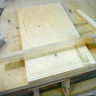
Spike making product
Made of wood and plywood, the jig shown above allows cutting rectangular spikes with two shoulders. The object to be machined is located with the front surface below the jig, while the router moves along the stop from above, removing the excess in two passes.
The piece consists of two parallel base bars, a stopper and a stop, all made from wood the same thickness as the piece, in this case 25x75mm bars, and a top and support made from 18mm plywood.
Base bars should be approximately 400 mm long; cut the top surface of the plywood approximately 200mm x 250mm and screw it to the joists as shown in the picture. Screw the stopper on the ends of the base bars along with the support. Set the stop approximately 25mm from the end of the top surface.

cutting out a thorn with a device
Countersink holes for all screw heads and make sure to make all corners square. Drill an inspection hole in the top surface to accurately place the workpiece exactly on the marking.
How to make a tongue and groove connection?
Spike and groove - what is it?
First of all, you should determine what a spike and a groove are. This is nothing more than a way to connect parts.
It is used most often in carpentry, as well as in other types of production. There are many types of grooves and spikes, but we'll talk about that another time.
Correctly made spikes and grooves are firmly connected to each other. This connection is considered one of the most durable.
tongue and groove connection method

First you need to determine for what purpose this connection method is needed. If this is a table, then the jumpers in it are usually connected to vertical legs.
Consequently, the fibers of the tree run vertically and horizontally. If this is a wall table or a bedside table with drawers, then the jumpers here will be located a little differently. They will be horizontal relative to the legs.
In any case, such a connection will be the most reliable. When performing a large number of thorn-groove joints, special machines are used. If you need one or more tenon-groove places, and there is no carpentry equipment at hand, then it would be advisable to do this manually. To do this, you need a set of carpentry tools, including:
- hacksaw;
- clamp - 2 pieces;
- measuring tool;
- marking pencil.
First, we will make a spike for the future connection.
To do this, you need to take the bar and mark on it the dimensions of the future spike.

First, note the length of the spike. We do this on all surfaces of the workpiece.


After that, we put the workpiece on the table, on it along the transverse line of the length of the spike we expose an even bar and fix it with a clamp. This is necessary in order to get a perfectly perpendicular cut.


We make cuts along the marked perimeter of the tenon length, rearranging the bar with the clamp.
We proceed to sawing the section of the spike.

We fix the workpiece to the table with a clamp in a vertical position.


To obtain a straight cut, we will use a pre-prepared T-shaped template. It is a plywood plate with a bar attached to it, as in the photo. We attach the template to the workpiece with a clamp. Next, we make cuts from the wide sides of the spike.


On the narrow sides of the section, if it is small, cuts can be made without the use of a T-shaped template. It is important to control the position of the hacksaw blade, it must be strictly parallel to the workpiece.

As a result, we get a high-quality spike according to the given dimensions.
We proceed to the manufacture of the groove.

Again, let's start with the markup. On the workpiece at the junction of the tenon-groove, we apply the size of the section of the tenon.


We fix the workpiece with a clamp on the table. If the workpiece is thin, then for ease of fastening we take several parts or a board of the appropriate size and fasten them with a clamp, as shown in the photo.

First, we cut a hole in width, to ensure perpendicularity, the chisel is set in a corner.


We perform a deepening to a given size, according to the mark of the length of the spike, having previously applied it to the sting of the chisel.

After the specified depth is reached, we clean the groove and insert the part with a spike.

The thorn-groove connection is ready.
How to make a tongue and groove connection correctly? A few more subtleties
Not being able to make a tongue-and-groove connection on a special machine, it can be done at home with high quality, according to the method of Yu. A. Egorov.
To do this, you need to calculate the width of the cut of the saw, which can be determined by the size of the setting of the teeth. You only need to make a few cuts on any bar.

Getting directly to work, we measure the thickness of the first part (the future spike) and put a line on the intended groove location on the second part.
Now we attach both parts one to the other so that their ends coincide. On the side faces, relative to each other, we shift them to the width of the cut.
We fix the parts in the workbench and make cuts evenly across the width. In the case of different thicknesses of parts, a thinner part contains deeper cuts and vice versa. We pay special attention to the fact that the cuts do not create cone-shaped spikes.
If the shift is less than the width of the cut, the parts will be tight. This will be important for any kind of furniture fixtures.

By making the shift greater than the width of the cut, the normal operation of the detachable fasteners (on the hairpin) is ensured.
Observing the depth and length of the cuts, we make new ones in the middle of the spikes we do not need. After that, we carefully remove the spikes that are unsuitable for us with a chisel, getting grooves from them, and clean them.
If the connection is supposed to be one-piece, it is put on glue and the entire product is ground.
How to make a tongue and groove connection with a router
The thorn groove of the connection, as we can see, can be done manually. However, if there are a lot of tongue and groove connections, it is better to use a router. A milling cutter with a desktop will be especially useful in such cases.
To facilitate the process of obtaining a hole in the workpiece for connecting the tenon-groove with a milling cutter in large quantities, for example, the manufacture of stools, a jig can be made.

Then making grooves will take you a few minutes.

To do this, initially, limiters in the form of rails are installed on the plywood sheet and holes are cut to the size of the required groove for the drawstring and proleg. Two rails are mounted along the width of the router, limiting the transverse shift, the other two are set taking into account the length of the device and the size of the groove.


We attach two bars to the table, corresponding in size to the workpiece, so that it can move freely along the length.


We expose and fix the emphasis.

Then we fix the device with screws to the bars on the table.

We take equipment equipped with a straight cutter and set the depth of milling. We do this with the help of a ready-made sample.

We set the milling depth taking into account the thickness of the conductor.

A prerequisite for milling is the fastening of the workpiece with a clamp, otherwise it may move under the force of the cutter.

After that, we directly process the groove.

The groove hole is ready.
We turn to the manufacture of the spike. In small-scale production, it is convenient to do this on a circular saw.


We begin the manufacture of the spike by measuring the groove. The depth of the groove will be the length of the tenon.


We set the size of the groove length on the machine, taking into account the width of the tool. We set the circular saw at the level of half the difference between the width of the workpiece and the length of the groove from the table surface. After we make two cuts along the length of the spike. Trial cuts when setting up a circular saw are best done on an unnecessary piece of wood, otherwise you can ruin a good part.


The preparatory work has been completed. We proceed to the direct cutting of the spike.


To do this, we set the circular saw to the size of the tenon length, and the size from the cutting tool to the stop, as half the difference between the width of the workpiece and the length of the groove. We make two cuts along the width of the workpiece from opposite sides.


The next operation will be to change the size from the tool to the stop. In this case, the distance will be equal to half the difference between the height of the workpiece and the width of the groove. We make the two remaining cuts.


Now we take a carpenter's knife and round off the corners of the spike.


- To create an opening for retractable drawers, you need to install two jumpers, although the gluing surface will decrease on the spikes.
- To increase the bonding area, and, consequently, its strength, we will use double spikes and grooves.
- To determine the length of the grooves, mark the upper and lower ends on each part. The field of this, to determine the width of the grooves, mark their sides.
- Clamp the straight cutter in the machine and set the ruler. We drill a groove with holes and clean it with a chisel.
- On the circular saw, we make all the cuts for double spikes.
- The distance between the longitudinal ruler and the outer side of the disk determines the length of the tenon. Waste wood is thrown away.
- We go smoothly to the pencil marks. We clean the remaining scallops from the circular for an accurate fit.
- We put the part on the end for cutting out internal lines. The constraint block helps support the part.
- We raise the disk almost to the shoulder pad in order to cut out the inner sides. After that, we press the limiter block and cut out the remaining inner part.
- We press the opposite face of the part to the limiter block without changing the setting of the disk.
- We check the fit of the spikes to the grooves. We cut the shoulder pads with a chisel.
- If necessary, remove irregularities.
- We cut the shoulders so that the spikes are completely seated in the grooves.
Thus, we examined some types of spikes and grooves that can be made both by ourselves and by ordering at the factory.
Although metal guides and all kinds of new fasteners have come into fashion lately, the tongue and groove connection still deserves respect and is one of the most durable connections.
Using it not only in woodworking products, various enterprises began to produce better products.
And also you can watch a video of making spikes on a table circular
Tailored for you:
Quite a lot has already been written about such tenon cutters, so I do not pretend to originality. But the thing in the workshop is definitely useful. Therefore, having assembled a tenon cutter for a straight box tenon, I decided to talk about it in my blog.
Such tenon cutters are usually made on the basis of a milling table or a circular saw. But, of course, options are also possible - depending on the invention of the master - on a band saw, a jigsaw machine, or even on a chainsaw!
I did not become original and made a device for cutting a straight box tenon for my router table (more about it here:).
Sometimes they use bearings and different guides to facilitate sliding, but I decided to do without them. The only condition is that the opposite edges of the table must be parallel. To do this, you can walk on them with a router with an emphasis on the other edge.
The first step is to cut out the base of the future tenon cutter from plywood. The dimensions of this base depend on the table itself - it must be wider than the table by the width of the side stops. I took stops of about 4 cm. The length of the stops should be the same or slightly less than the width of the table - then they will not wedge. I glued all the details of the tenon cutter with carpentry glue and fixed it with self-tapping screws - perhaps redundantly, but I wanted to.

All screw heads are recessed.

To select the correct position of the second stop, we put the workpiece with the first stop installed on the table, resting it (the first stop) against the edge of the table, apply glue to the second stop ...

And having laid a sheet of paper between the second stop and the edge, we fix it (the second stop) in this position with clamps. The gap left by the paper will be ideal for the tenon cutter to move freely along the edges of the table without dangling.


For purely aesthetic reasons, we cut the edge so that the stops are flush with the main part.

The carriage for our tenon cutter is ready

Next, a stop will be installed on this carriage, which can be adjusted and which must always be perpendicular to the direction of movement of the carriage. In order not to check this perpendicularity every time, I made a ledge with the right angles on the edge of the carriage.

On the same ledge, using the M8 bolt, I installed the handle from the adjusting mechanism of the office chair.

The handle is located exactly in the middle between the stops - this is another degree of protection against carriage jamming. The handle is quite grippy and secure. It also sets a safe position for the right hand. It is convenient to use it.


The stop is fixed with two M10 bolts with recessed heads and wing nuts. The stop can move along the ledge with the handle in both directions.

It is important that the plane of the stop is perpendicular to the plane of the carriage.

The carriage is made of 18 mm FSF plywood. I'm sure many are now choking - where such a thickness, it's some kind of monster! Well, yes, it could be made thinner, but I like things with excess strength where possible. Here is my feature.
Therefore, the cutter had to buy a special one. All characteristics and articles are visible in the photo.


We insert the pin into the resulting groove. I made it from textolite 6 mm thick.

The device is ready. The design is quite simple, it took longer to tell than to do))

The first run showed that in general the device works, but requires configuration

Careful adjustment requires the height of the cutter and the width of the tenon. After a while it started working.

It is more convenient to process parts in packages - at least two. At the same time, the outer parts have a hard time - a straight cutter mercilessly pulls out of them not just individual fibers, but entire layers. Therefore, the details must be processed, wrapping them on both sides with unnecessary bars.

See what happened to the parts that were external in the package. I don’t know how in magazines and videos they manage to process the details one by one. You can use spiral cutters - maybe this will solve the problem, but they are usually several times more expensive than straight ones.

Therefore, we simply wrap the workpieces on both sides and get an excellent result. Here it is also necessary not to lose sight of which side and in what sequence to process the parts so that they then form into a product.

In general, the result is not bad. These were test bars, but since it turned out well, I decided to finish the job and make a box.

Cut out the bottom of the box on a circular saw


And then another nuance came out - for grinding protruding spikes, a device for cutting a straight box spike should be equipped with a belt grinder or a disc grinder or something like that. An eccentric sander does not cope, filling up the edges. Otherwise, I'm happy with the purchase - it works as it should.

Related Articles