El scheme of a table fluorescent lamp with a power of 9 watts. The device and circuit for switching on a fluorescent lamp
A fluorescent light bulb can be found in almost any room today. It is a source of daylight and makes it possible to save energy. Therefore, such lamps are also called housekeepers.
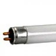
The appearance of a fluorescent lamp
But such products have one significant drawback - they burn out. And the reason for this is the combustion of the electronic filling - the throttle or starter. This article will tell you if there is a way to connect fluorescent lamps without using a choke in the electrical circuit.
How the housekeeper works
The appearance of fluorescent lamps may be different. Despite this, they have the same principle of operation, which is realized thanks to the following elements, which are usually contained in the device circuit:
- electrodes;
- phosphor - a special luminescent coating;
- glass flask with an inert gas and mercury vapor inside.

The structure of a fluorescent light bulb
Such a fluorescent lamp is a gas discharge device with a sealed glass bulb. The gas mixture inside the flask is selected in such a way as to reduce the energy required to support the ionization process.
Note! For such lamps, in order to maintain the glow, you need to create a glow discharge.
To do this, a voltage of a specific value is applied to the electrodes of a fluorescent lamp. They are located on opposite sides of the glass bulb. Each electrode has two contacts that are connected to a current source. Thus, the space near the electrodes is heated.
The actual wiring diagram for this light source consists of a series of sequential steps:
- electrode heating;
- then a high-voltage pulse is applied to them;
- the optimal voltage is maintained in the electrical circuit to create a glow discharge.
As a result, an ultraviolet invisible glow is formed in the flask, which, passing through the phosphor, becomes visible to the human eye.
To maintain voltage to create a glow discharge, the operation of fluorescent lamps involves connecting the following devices:
- throttle. It acts as a ballast and is designed to limit the current flowing through the device to an optimal level;

Choke for fluorescent bulbs
- starter. It is designed to protect the fluorescent lamp from overheating. At the same time, it regulates the incandescence of the electrodes.
Very often, the reason for the breakdown of housekeepers is the failure of the electronic filling of the ballast or the burnout of the starter. To avoid this, you can not use burnt parts in the connection.

Standard Connection Diagram
The standard circuit used to connect fluorescent lamps can be modified (go without a choke). This will minimize the risk of failure of the lighting fixture.

Switching option without ballast
As we found out, the ballast in the device of a fluorescent lamp plays an important role. At the same time, today there is a scheme in which it is possible to avoid the inclusion of this element, which very often fails. It is possible to avoid including both the ballast and the starter.
Pay attention! This connection method can also be used for burnt out daylight tubes.
As you can see, this circuit does not contain a filament. In this case, the lamps / tubes will be powered here through a diode bridge, which will create an increased DC voltage. But in such a situation, it must be remembered that with this method of power supply, the lighting product may darken on one side.
In implementation, the above scheme is quite simple. It can be implemented using old components. For this type of connection, you can use the following elements:
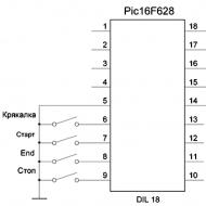
- handset/light source 18 W;
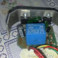
- assembly GBU 408. It will act as a diode bridge;

Diode bridge
- capacitors with an operating voltage not exceeding 1000 V, having a capacitance of 2 and 3 nF.
Note! When using more powerful light sources, it is necessary to increase the capacitance of the capacitors used in the circuit.

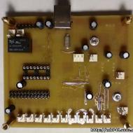
Assembled Circuit
It must be remembered that the selection of diodes for the diode bridge, as well as capacitors, must be carried out with a voltage margin.
A lighting device assembled in this way will give a glow slightly less in brightness than when using the standard connection option using a choke and starter.
What allows you to achieve a non-standard connection option
A change in the usual way of connecting electrical components in fluorescent lamps is carried out in order to minimize the risk of breakage of the device. Fluorescent lamps, despite the presence of impressive advantages, such as excellent luminous flux and low power consumption, have some disadvantages. These should include:
- during their work they produce a certain noise (buzz), which is due to the functioning of the ballast element;
- high risk of starter burnout;
- the possibility of overheating the filament.
The above scheme for connecting the components of the electrical circuit will avoid all these disadvantages. When using it, you will receive:
- a light bulb that will light up instantly;

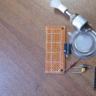
What does assembly look like?
- the device will work silently;
- there is no starter, which burns out more often than other parts with frequent use of the lighting installation;
- it becomes possible to use a lamp with a burnt filament.
Here, the role of the throttle will be performed by an ordinary incandescent bulb. Therefore, in such a situation, there is no need to use an expensive and rather bulky ballast.
Another connection option
There is also a slightly different suitable scheme:

Another connection option
It also uses a standard light source with a power approximately equal to a fluorescent lamp. In this case, the device itself must be connected to the power supply through a rectifier. It is assembled according to the classical scheme, used to double the voltage: VD1, VD2, C1 and C2.
This connection option is as follows:
- at the moment of switching on, there is no discharge inside the glass bulb;
- then twice the mains voltage falls on it. Thanks to this, light is ignited;
- activation of the device occurs without preheating of the cathodes;
- after starting the electrical circuit, the current-limiting lamp (HL1) is turned on;
- at the same time, HL2 establishes the operating voltage and current. As a result, the incandescent lamp will barely glow.
In order for the start to be reliable, you need to connect the phase output of the network to the current-limiting lamp HL1.
In addition to this method, other variations of the standard switching scheme can be used.
Conclusion
Using modifications to the usual method of connecting fluorescent lamps, an element such as a choke can be excluded from the electrical circuit. In this case, it is possible to minimize the negative effect (for example, noise) that is observed during the operation of a standard lighting installation of this type.
 Choosing a box for LED strips, correct installation
Modern society seeks to save on all types of energy carriers, especially on electricity. This is due to the constant increase in electricity bills. Therefore, fluorescent lamps are very firmly included in people's lives and are actively used.
What are daylight bulbs made of?
The lamp itself consists of a glass bulb, which can be of various shapes and diameters. According to their structure and appearance, they are divided:
- compact with base E 14 and E 27;
- ring;
- U-shaped;
- straight.
Regardless of the appearance, each of the fluorescent lamps has electrodes inside, a special luminescent coating, and an inert gas injected with mercury vapor. Due to the fact that the electrodes are heated, the inert gas is periodically ignited, so the phosphor glows. Given that the coils can overheat and burn out during short-term heating, these devices use a starter for fluorescent lamps. It is worth noting the fact that the spirals in daylight illuminators are small in size, the standard voltage is not suitable for them, therefore special devices are installed - chokes, the task of which is to limit the nominal value of the current strength.
The principle of operation of a fluorescent lamp
When the illuminator is connected to the network, there is an automatic mains voltage supply 220 V on the diagram, then it follows the starter. Since the contacts are still open, the full voltage does not go through the device, but falls on the inductor, where it fluctuates around zero. This voltage is sufficient to ignite the discharge in the light bulb. As soon as the bimetallic electrode of the starter warms up, it bends and the electrical circuit is closed, the filaments in the fluorescent lamp light up. This causes the lamp itself to start working.
As electrodes in fluorescent lamps, tungsten filament. They must be coated with a special protective paste. After a while, this paste burns out, which causes the filament to burn out. If at least one of the threads burns out, the illuminator fails and will not light up.
How to connect the lighting fixture
There are wiring diagrams for fluorescent lamps. They are very simple and do not cause difficulties even for an inexperienced person. For one light source, it is enough to apply voltage to the assembled circuit through the terminals. It will follow the throttle, then the first spiral. Then, the starter turns on, it reacts to the incoming current, and passes it further to the second spiral connected to the terminal.
If you need to install several daylight fixtures, then the wiring diagrams will change slightly. All lamps will be connected in series. Several starters will be used, for each source separately. If you want to install two lamps on one choke, then you need to read the rated power, which is indicated on the body. If the throttle power is 40 W, then only two devices with a power of 20 W are connected to it.
Lamp connection diagrams have been developed without starter. They are replaced by electronic ballast devices. In this embodiment, the daylight device turns on instantly, there is no blinking, as when the starter is turned on.
Connecting electronic ballasts is easy. To do this, just read the instructions that are on the device. Such instructions indicate the connection diagram, which lamp contacts should be connected to the corresponding terminals. It is worth noting that many experts believe that this particular method has great advantages:
- you do not need additional elements to control and connect the starter;
- the operation of the lamp without a starter is longer, since the installation of the connecting wires of the device and the starter, which often and quickly fail, is excluded.
It is worth noting that connecting fluorescent incandescent lamps is not difficult, since all the necessary elements of the device and their assembly diagrams are included with the device. You do not need to buy something extra and invent or look for device assembly schemes.
Fluorescent lamp breakdowns, repair and replacement
 As soon as you find problems in the operation of the device, you need to find out the causes of the malfunction, and decide whether a complete replacement of the lamp is needed, or it is enough to install a new element. The most common malfunctions are starter or throttle problems. When the lamp, when turned on, lights up only on one side, it is necessary to turn it over so that the entrance of the non-luminous part is in the opposite place. In the case when the lamp continues to shine in the same way, then it can be thrown away - it is faulty.
Often there are problems when two ends of the lamp are lit, but the whole of it does not light up. This may indicate a malfunction of the starter, wiring or cartridge. Start checking from the starter. If it is working, then start working with the wiring, perhaps there are short circuits in it.
If the lamp, when turned on, lights up with a dim light, and after a few minutes it begins to pulsate and goes out altogether, then this indicates about air getting into the flask. In this case, the device needs to be replaced.
How the throttle works, the main signs of failure
Some lamps ignite abruptly and instantly, but after several hours of operation, the edges of the light source darken. This work deserves immediate attention. This indicates a rapid failure of the device. The cause of the breakdown will be a problem in the operation of the inductor: the starting and operating current have indicators that exceed the norm. For an accurate diagnosis of the problem, it is enough use a voltmeter, and check the value of the starting and operating current. Most often, specialists find faults in several cathodes.
Some users observe that a snake periodically winds in a fluorescent lamp. It also indicates a problem with the throttle. An electrical voltage is supplied to the source, but the discharge inside is uneven. Here it is also enough to check the value of the starting and operating voltage, and if an excess is detected, replace the inductor with a new one.
The main problems in the starter
 When the owner of a fluorescent lamp observes a picture of a constantly or periodically fading device, this indicates problems in the operation of the starter and lamp. For accurate troubleshooting, you need to check input voltage in the device. If its parameters are much higher, then it is enough to replace only the lamp. Be sure to measure the voltage at the starter as well. If it is below normal, then the starter needs to be replaced.
If the fluorescent lamp starts to function dimly, then this is a sign of a sharp decrease in current inside to a critical level. This indicates a problem with the throttle. When you measured the voltage in it and made sure that there were no reasons for improper operation, then perhaps your light source has served its time, the amount of mercury inside has decreased to a minimum. The bulb itself needs to be replaced.
If the spiral burns out in the lamps, then this indicates a breakdown or damage to the throttle. Most often, these are problems or deterioration of the insulation. As soon as the fluorescent light source stops working normally, it is necessary to immediately disconnect it from electricity and find the causes of the breakdown. Do not repeatedly try to turn on the device, as the failure of one element leads to problems in operation or failure of other parts of the device.
It is important to understand the main thing - when installing a fluorescent lamp, the connection diagrams must be operated correctly. Only in this case there will be no problems and the device will function efficiently.
Fluorescent lamps from the very first releases and partially still ignite with the help of electromagnetic ballasts - EMPRA. The classic version of the lamp is made in the form of a sealed glass tube with pins at the ends.
What do fluorescent lamps look like?
Inside it is filled with an inert gas with mercury vapor. Its installation is carried out in cartridges through which voltage is applied to the electrodes. An electric discharge is created between them, causing an ultraviolet glow, which acts on a layer of phosphor deposited on the inner surface of the glass tube. The result is a bright glow. The circuit for switching on fluorescent lamps (LL) is provided by two main elements: an electromagnetic ballast L1 and a glow discharge lamp SF1.

LL switching circuit with electromagnetic choke and starter
Ignition circuits with EMPRA
A device with a throttle and a starter works according to the following principle:
- Applying voltage to the electrodes. The current through the gas medium of the lamp at first does not pass due to its high resistance. It enters through the starter (St) (fig. below), in which a glow discharge is formed. In this case, a current passes through the spirals of the electrodes (2) and begins to heat them.
- The starter contacts warm up, and one of them closes, since it is made of bimetal. The current passes through them, and the discharge stops.
- The starter contacts stop warming up, and after cooling, the bimetallic contact opens again. In the throttle (D), a voltage pulse arises due to self-induction, which is sufficient to ignite the LL.
- A current passes through the gaseous medium of the lamp; after starting the lamp, it decreases along with the voltage drop across the inductor. The starter remains disabled, since this current is not enough to start it.

Fluorescent lamp switching circuit
Capacitors (C 1) and (C 2) in the circuit are designed to reduce the level of interference. Capacitance (C 1), connected in parallel with the lamp, helps to reduce the amplitude of the voltage pulse and increase its duration. As a result, the service life of the starter and LL is increased. The capacitor (C 2) at the input provides a significant reduction in the reactive component of the load (cos φ increases from 0.6 to 0.9).
If you know how to connect a fluorescent lamp with burnt out filaments, it can be used in the CMP circuit after a slight change in the circuit itself. To do this, the coils are short-circuited and a capacitor is connected in series to the starter. According to this scheme, the light source will be able to work for some more time.
The switching method with one throttle and two fluorescent lamps is widespread.

Switching on two fluorescent lamps with a common choke
2 lamps are connected in series with each other and the inductor. Each of them requires the installation of a starter connected in parallel. For this, one output pin is used from the ends of the lamp.
For LL, it is necessary to use special switches so that their contacts do not stick from high inrush current.
Ignition without electromagnetic ballast
To extend the life of burned-out fluorescent lamps, you can install one of the switching circuits without a choke and starter. For this, voltage multipliers are used.

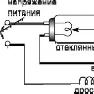
Scheme for switching on fluorescent lamps without a choke
The filaments are short-circuited and voltage is applied to the circuit. After straightening, it increases by 2 times, and this is enough for the lamp to light up. Capacitors (C 1), (C 2) are selected for a voltage of 600 V, and (C 3), (C 4) - for 1000 V.
The method is also suitable for serviceable LLs, but they should not work with DC power. After some time, mercury collects around one of the electrodes, and the brightness of the glow decreases. To restore it, you need to turn the lamp over, thereby changing the polarity.
Connection without starter
The use of a starter increases the warm-up time of the lamp. At the same time, its service life is short. Electrodes can be heated without it if secondary transformer windings are installed for this.

Wiring diagram for a fluorescent lamp without a starter
Where a starter is not used, the lamp has a quick start designation - RS. If you install such a lamp with a starter start, it can quickly burn out the spirals, since they have a longer warm-up time.
Electronic ballast
The electronic control circuit of the electronic ballast has replaced the old sources of daylight to eliminate their inherent shortcomings. The electromagnetic ballast consumes excess energy, often makes noise, fails and at the same time spoils the lamp. In addition, the luminaires flicker due to the low frequency of the supply voltage.
Electronic ballast is an electronic unit that takes up little space. Fluorescent luminaires start quickly and easily, without creating noise and providing uniform illumination. The circuit provides several ways to protect the lamp, which increases the service life and makes it safer to work.
The electronic ballast works as follows:
- Heating of LL electrodes. Startup is fast and smooth, extending lamp life.
- Ignition - generating a high voltage pulse that breaks through the gas in the flask.
- Combustion - maintaining a small voltage on the electrodes of the lamp, which is sufficient for a stable process.

Electronic choke circuit
First, the alternating voltage is rectified using a diode bridge and smoothed out by a capacitor (C 2). Next, a half-bridge high-frequency voltage generator on two transistors is installed. The load is a toroidal transformer with windings (W1), (W2), (W3), two of them are connected in antiphase. They alternately open the transistor switches. The third winding (W3) supplies the resonant voltage to the LL.
A capacitor (C 4) is connected in parallel with the lamp. The resonant voltage is applied to the electrodes and breaks through the gaseous medium. By this time, the filaments have already warmed up. After ignition, the resistance of the lamp drops sharply, causing the voltage to drop to a sufficient value to keep the lamp burning. The startup process takes less than 1 s.
Electronic circuits have the following advantages:
- start with any given time delay;
- installation of a starter and a massive throttle is not required;
- the lamp does not blink and does not buzz;
- high-quality light output;
- device compactness.
The use of electronic ballasts makes it possible to install it in the lamp base, which was also reduced to the size of an incandescent lamp. This gave rise to new energy-saving lamps that can be screwed into a regular standard socket.
During operation, fluorescent lamps age and require an increase in operating voltage. In the EMP circuit, the ignition voltage of the glow discharge at the starter is reduced. In this case, an opening of its electrodes may occur, which will cause the starter to operate and turn off the LL. After that it starts up again. Such a flashing of the lamp leads to its failure along with the throttle. In the electronic ballast circuit, this phenomenon does not occur, since the electronic ballast automatically adjusts to changes in the parameters of the lamp, choosing a favorable mode for it.
Lamp repair. Video
Tips for repairing a fluorescent lamp can be obtained from this video.
LL devices and circuits for their inclusion are constantly evolving in the direction of improving technical characteristics. It is important to be able to choose the right models and operate them correctly.
If the old Soviet luminaire with fluorescent fluorescent lamps such as LB-40, LB-80 is out of order, or you are tired of changing the starter in it, disposing of the lamps themselves (and you can’t just throw them in the trash for a long time), then you can easily convert to LED.
Most importantly, fluorescent and LED lamps have the same base - G13. No upgrade of the housing, unlike other types of pin contacts, is required. 
- G- means that pins are used as contacts
- 13 is the distance in millimeters between these pins

Rework Benefits
In doing so, you will receive:

- greater illumination
- lower losses (almost half of the useful energy in fluorescent lamps can be lost in the inductor)
- lack of vibration and nasty rattling sound from the ballast throttle
 True, in more modern models, electronic ballast is already used. They increased efficiency (90% or more), noise disappeared, but energy consumption and luminous flux remained at the same level.
For example, new models of such LPO and LVO are often used for Armstrong ceilings. Here is a rough comparison of their effectiveness: 
Another advantage of LED - there are models designed for supply voltages from 85V to 265V. For fluorescent you need 220V or close to it. 
For such Led, even if the mains voltage is weak or too high, they will start up and shine without any complaints.
Luminaires with electromagnetic control gear
What should I pay attention to when converting simple fluorescent fixtures to LED? First of all, its design. 
If you have a simple old Soviet-style lamp with starters and an ordinary (not electronic gear) throttle, then in fact you don’t need to upgrade anything. 
Just pull out the starter, select a new LED lamp according to the overall size, insert it into the housing and enjoy brighter and more economical lighting.

If the starter is not removed from the circuit, then when replacing the LB lamp with an LED one, a short circuit can be created.
The throttle does not need to be removed. For LED, the current consumption will be within 0.12A-0.16A, and for the ballast, the operating current in such old lamps is 0.37A-0.43A, depending on the power. In fact, it will play the role of an ordinary jumper. 
After all the alteration, the lamp you have remains the same. There is no need to change the mount on the ceiling, and the burned-out lamps will no longer have to be disposed of and look for special containers for them. 
For such lamps, separate drivers and power supplies are not needed, since they are already built-in inside the case. 
The main thing is to remember the main feature - for LEDs, two pin contacts on the base are rigidly connected to each other.

And in luminescent they are connected by a filament. When it is heated, the mercury vapor ignites. 
In models with electronic control gear, no filament is used and the gap between the contacts is broken by a high voltage pulse.
The most common sizes of such tubes:
- 300mm (used in table lamps)

- 900mm and 1200mm
The longer their length, the brighter the glow. 
Alteration of the lamp with electronic control gear
If you have a more modern model, without a starter, with an electronic ballast (electronic ballast), then you will have to tinker a bit with changing the circuit. 
What is inside the lamp before alteration:
- throttle
- wires
- contact pads-cartridges on the sides of the case
The choke is what needs to be thrown out first. Without it, the entire structure will significantly lose weight. Unscrew the mounting screws or drill out the rivets, depending on the fastener.
Then disconnect the power wires. You may need a narrow-bladed screwdriver to do this. 
You can wire these and just have a bite to eat with pliers.
The connection diagram of the two lamps is different, on the LED everything is done much easier: 
The main task that needs to be solved is to apply 220V to different ends of the lamp. That is, the phase is on one output (for example, the right one), and zero on the other (left). 
Earlier it was said that for an LED lamp, both pin contacts inside the base are interconnected by a jumper. Therefore, here it is impossible, as in a fluorescent one, to supply 220V between them.
Use a multimeter to verify this. Set it to the resistance measurement mode, and touch the two leads with the test probes to measure. 
The display should show the same values as when the probes are connected to each other, i.e. zero or close to it (taking into account the resistance of the probes themselves).
The fluorescent lamp, between the two terminals on each side, has the resistance of the filament, which, after applying a voltage of 220V through it, warms up and “starts” the lamp. 
- without dismantling cartridges
- with dismantling and installation of jumpers through their contacts
without dismantling
The easiest way is without dismantling, but you will have to buy a couple of Wago clamps.
In general, you bite out all the wires suitable for the cartridge at a distance of 10-15mm or more. Then put them into the same Vago clip. 
Do the same with the other side of the lamp. If the wago terminal block does not have enough contacts, you will have to use 2 pcs. 
After that, all that remains is to apply phase to the clamp on one side, and zero on the other.
No Vago, just twist the wires under the PPE cap. With this method, you do not need to deal with the existing circuit, with jumpers, climb into the contacts of the cartridges, etc.
With the dismantling of cartridges and the installation of jumpers
Another method is more scrupulous, but does not require any extra costs.
Remove the side covers from the lamp. This must be done carefully, because. in modern products, the latches are made of fragile and brittle plastic. 
After that, you can dismantle the contact cartridges. Inside them are two contacts that are isolated from each other.
Such cartridges can be of several varieties: 
All of them are equally suitable for lamps with a G13 base. They may have springs inside. 
First of all, they are needed not for better contact, but so that the lamp does not fall out of it. Plus, due to the springs, there is some compensation for the size of the length. Since with an accuracy of up to a millimeter, it is not always possible to make identical lamps.
There are two power wires for each cartridge. Most often, they are attached by snapping into special screwless contacts. 
Turn them clockwise and counterclockwise, and with an effort pull out one of them. 
As mentioned above, the pins inside the connector are isolated from each other. And by dismantling one of the wires, you actually leave one contact socket out of your hands. 
All current will now flow through the other pin. Of course, everything will work on one, but if you are making a lamp for yourself, it makes sense to slightly improve the design by placing a jumper.
Thanks to her, you do not have to catch the contact by turning the LED lamp around. The double connector ensures a secure connection. 
The jumper can be made from the extra power wires of the lamp itself, which you will definitely have as a result of the alteration.
With a tester, you check that after installing the jumper, there is a circuit between the previously isolated connectors. Do the same with the second plug-in contact on the other side of the lamp.
The main thing is to make sure that the remaining power wire is no longer phase, but zero. You bite the rest.
Fluorescent lamps for two, four or more lamps
If you have a two-lamp lamp, it is best to supply voltage to each connector with separate conductors. 
When installing a simple jumper between two or more cartridges, the design will have a significant drawback.
The second lamp will glow only if the first one is installed in its place. Remove it, and the other one will immediately go out. 
The supply conductors must converge on the terminal block, where in turn you will have connected: 
Reading time ≈ 3 minutes
The most common source of lighting used in office, industrial and public buildings are fluorescent lamps. Recently, in connection with energy savings, they also began to be often used in home life.
Standard lamps, in addition to their advantages, such as low power consumption, ease of installation, low cost, have a number of design flaws. Some of them emerge from the merits: using cheap, outdated schemes and materials, the manufacturer reduces the cost of the lamp, while deteriorating consumer qualities in advance.
Wiring diagram for fluorescent lamps

The connection of one or two factory-made fluorescent lamps can be studied by disassembling an ordinary lamp. The usual standard, widely used fluorescent lamp connection scheme includes a starter, a choke, connecting wires, a capacitor, and the lamps themselves. In this case, the so-called electromagnetic control system is used.
It is quite possible to improve the degree of illumination on your own, to remove the annoying buzz and blinking. To do this, it is necessary to replace the outdated control system with a modern electronic one - (electronic ballast).

First, you need to dismantle the lamp, remove all the stuffing from it. By purchasing a new electronic unit, based on the parameters of your lamp, it will be possible to connect fluorescent lamps without a choke and starter. For such work, you will need screwdrivers with different stings, wire strippers, a screwdriver for attaching control units, electrical tape, a tester screwdriver.
Connecting electronic ballasts for fluorescent lamps is easy to do with minimal knowledge of electrical circuits and wiring skills. In fact, the unit itself, a set of wires and fluorescent lamps will remain in the lamp.

Before starting work, you need to choose a sufficient place in the luminaire housing for installing the electronic control unit, guided by the convenience of connecting to the terminals located on its housing. We fix the block to the body with the help of self-tapping screws with an ordinary screwdriver. We connect the control equipment with the lamp and the connection terminal.
The connection scheme for 2 fluorescent lamps is similar, they are simply connected in series, and, based on this, the power of the electronic unit should be twice the power of the lamps. The same principle, when connecting three or more lamps, in one housing.

After assembling the entire structure, you need to make sure that all conductors are connected correctly, after which you can install the lamp in place. Having checked the absence of voltage in the network with a tester, we connect the lamp to the electrical wiring, connecting the wires through a special terminal block.
The last chord is the inclusion of voltage to verify the correct operation of the lamp. If the scheme, for example, connecting two fluorescent lamps, was performed correctly, then the work process itself will be very different from the original one. Firstly, the lamps will light up instantly, without the so-called warm-up, and secondly, the low-frequency buzz will disappear, the light will stop pulsing, noticeable to the human eye, and the overall luminosity will increase.
Related Articles