Radio circuits. Do-it-yourself sound piezo emitter Simple squeaker circuit
The circuit presented in this article is very easy to repeat and should not cause any difficulties in assembly.
It can be used in various devices for sound notification. For example, alarms, sound duplication of a turn signal in a car or bicycle, a low battery signal, and so on. Of course, you can take a ready-made beeper, for example, from an old Chinese alarm clock, a musical postcard or other devices, but I decided to make it myself. So it's more interesting.
Another purpose of the assembly is to popularize the youth hobby for radio electronics. If this site can captivate at least a few people with such an interesting and good deed, then its task can be considered completed.
The scheme took a simple, but proven. I don't even remember where I got it from.
Scheme of a sound piezo emitter
Parts for assembling the horn circuit
Details for the circuit can be used in a very wide range.For example, La7 microcircuits from the K176, K164, K564, K561 or K561LE5 series or imported analogues. In order not to solder and solder the microcircuit, it is best to take a special contact pad and solder it into the circuit (it costs a penny), and replacing the microcircuit will take seconds, moreover, during soldering there is no risk that the microcircuit will be overheated or damaged by static electricity. In addition, you can easily test different brands of microcircuits for performance.
Capacitor C1 is polar for a voltage of at least 15 volts, and with a capacity of 47 to 500 microfarads. If you want the buzzer to stop immediately after turning off the power, then this capacitor must be excluded, otherwise, after turning off the power, the sound continues until the capacitor is discharged.
Capacitor C2 ceramic from 0.1 to 0.47 microfarads. They are indicated by numbers on the cover - 104, 154, 224, 474.
Resistor R1 from 5 to 50 kilo ohms. Any power, but less is better. So that the dimensions are not large.
Potentiometer R2 from 68 to 500 kilo ohms. Same power, less power.
You can use any diode you like. It is used to protect the chip from improper power connection. You can do without it altogether.

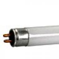
Sound emitter ZP-3 or any similar.

How to connect ZP-3? If the ZP-3 sound emitter is new, then you need to solder the wires to it, as in the photo. Solders easily with flux. We solder one wire to the membrane. Solder the second wire to either of the two leads.
The supply voltage of the circuit is 12 volts. It can be a battery, a rectifier, or any other DC source.
The tone of the sound of the device depends on the ratings of the circuit elements, so you can experiment by changing capacitors and resistors, achieving a sound that you like.
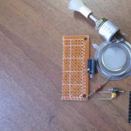
In order not to make a printed circuit board, it is best to take and use a breadboard, it turns out much easier and faster.


We place the parts more tightly on the breadboard, solder, check again and try the sound by connecting to a power source.

With proper assembly and serviceable parts, the circuit starts working immediately and does not need to be configured. If you do not like the tone, then adjust the potentiometer to your taste.
The alarm has been assembled.

Creating circuits for beginners is indeed a very difficult task. Every time you have to find a compromise between reliability, simplicity, repeatability, "not to be killed" and, at the same time, it (the scheme) must be interesting, able to lead and be informative. It is impossible to develop a device that will equally meet all these qualities in the same way for different age groups of students. And the younger they are, the harder it is to do it! In this article, I want to talk about designs that four graders repeat with pleasure. Yes, there is little novelty in circuit solutions (to say the least - no). But there is a system and reliability of structures, their high repeatability and low cost. And I will not bother with theory, because for a fourth grade student to know: this is a resistor, this is a capacitor, and this is a transistor and it has three legs (!!!) is already a great achievement. For the same reason, I will not give the PCB layout, since the etching of boards at this age it is forbidden according to the elementary rules of safety and common sense. Installation is carried out by a hinged method on a piece of cardboard under the guidance of a teacher or parent.
The “heart” of all the devices I am considering will be the simplest sound generator, made on a single-junction transistor KT117, and, through simple upgrades, we will get different consumer qualities.
Video of work:
Often such tweeters are called "mosquito repeller", but who would act as a voluntary donor and in practice would prove the effectiveness (not efficiency) of such devices? Personally, I prefer to use chemicals. But you need to somehow encourage the child to repeat the scheme! And so ... WE Frightened the mosquito!
It's just not fun to eat. Consistently with the battery, we install the key model and simulate the operation of the telegraph. And, be afraid of school teachers, it squeaks disgustingly, the tone is high, the location of the generator in space is hard to localize by ear. But when to brag about your design in front of peers if not in the classroom?
This scheme is easy to transform into a sound beacon. To do this, it is often recommended to power the entire generator through a flashing LED. This is not entirely true. Yes, the circuit will work, but the closed LED (it does not glow) still passes current through itself, since its p-n junctions are connected in the forward direction. The generation frequency of the circuit also depends on the supply voltage, as a result of which the sound is torn - a loud high tone alternates with a quiet low tone. This disadvantage can be eliminated by introducing control of the flashing LED on the second base of the transistor.

Video of work:
Another interesting transformation of the original scheme is the introduction of the dependence of the tone of the generator on the illumination. To do this, a PTR1 phototransistor should be introduced into the circuit, controlling a unijunction transistor from the emitter side with it. The generator squeaks even more disgustingly, but how much joy the child is caused by the fact that the sound is completely different at the window and inside the room!

Video of work:
And, of course, a two-tone siren, but how without it? Not a single police (police) car can do without it! To organize two-tone sounding, we introduce control of a unijunction transistor along the emitter using, again, a blinking LED. This design will be useful to insert into a toy car.

Video of work:
If you want to build a multi-tone automatic sound effects machine, then you need to use a three-color flashing diode as a control LED, or turn on three different diodes with different glows (red, blue, green as it is done). If you want to increase the sound volume, you must use any audio frequency amplifier, for this the speaker must be changed to a resistor with a resistance of 100 ohms and a signal for ULF must be removed from it.
The schemes I have considered allow stimulating younger students to study the very basics of radio electronics, can be useful in the system of additional education, do not contain a large number of details and do not cause difficulties in repeating them.
A single transistor watchdog is the simplest circuit that even a preschooler can assemble.
Are your properties often invaded without permission, while you are doing important business?)

It's time to forget these problems! I present to your attention the circuit of the watchdog on just ONE! Thanks to this scheme, you will be able to secure your home and take all necessary measures to eliminate the problems that have arisen in time!
Scheme and principle of operation
And here is the schematic

The pinout (pinout) of the KT815B transistor looks like this:

The principle of operation is very simple. When the security wire breaks, the buzzer starts beeping. A thin security wire can be pulled through the doorway.
To more accurately describe the operation of the circuit, it will look like this:
draw a diagram according to GOST for ease of perception
As long as we have a security wire intact, then in the circuit plus batteries - a 100 K resistor - the security wire will current flow. All current will flow through the guard wire, since its resistance is very small. Since all the current will flow through the wire, there won't be enough current to turn on the transistor. The transistor opens only when its voltage between the base and the emitter is 0.5-0.7 Volts.
But ... as soon as the security wire breaks, the voltage on the base immediately increases sharply, that is, it becomes more than 0.5-0.7 Volts and current begins to flow through the base-emitter. Since the current flows through the emitter base, the transistor turns on. And since it opens, it means that current begins to flow through the circuit plus batteries—buzzer—collector—emitter. As long as current flows through the buzzer, it yells like a scalded.
Assembly and work in practice
The circuit consists of a KT815 transistor with any letter. I took this one:

What's with the weird markings on the transistor? Previously, this is how Soviet transistors were designated. Experienced radio amateurs will immediately determine that this is a KT815B transistor. For beginners, I advise you to download the Transistor v1.0 program, which will allow you to easily identify Soviet transistors, even with color coding.
Here is an example of a transistor that I am using in a circuit:

The circuit also has a buzzer:

The buzzer is a sound emitter. When applying for it permanent voltage, it begins to squeak with a high-frequency unpleasant monotonous sound. I took it on Aliexpress for 0.7 bucks this link.
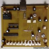
Buzzers are often confused with piezo emitters (below in the photo):
If we disassemble the buzzer, we will see on the scarf a simple circuit of a frequency generator made in SMD design, as well as the piezoelectric emitter itself, soldered with copper wires to this scarf.

So if you take a buzzer in a radio store, make sure that the seller does not slip you an ordinary piezo emitter.
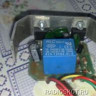
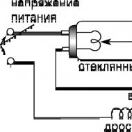
Instead of a buzzer, you can take a low-power light bulb or some kind of actuator that will be turned on through a relay. In this case, do not forget to protect the transistor by connecting a protective diode in parallel with the relay coil:

Well, here, in fact, is the video of the whole scheme. The orange wire is a type of security wiring.
A simple musical instrument can be made in less than half an hour. Of course, the range of its sound, frequency, and as a result, the tone is very different from real professional instruments, but due to its simplicity, it will be an excellent device for assembling a beginner electronics engineer.

The basis of the circuit is the well-known and mega-popular microcircuit 555, its period, and hence the frequency, can be controlled using the values of some resistances of the resistors and the capacitance of the capacitor.

As you can see, we have a lot of resistors with different ratings, so by pressing a certain key you turn on a resistor of a certain resistance in the circuit and a sound is heard in the sound-emitting device. By pressing another key, with a different resistor, you will create sound vibrations with a different tone. When you press two or more buttons, the resistors are connected in parallel, a different resistance is created and the sound changes. Combining these pressings in a certain sequence, you can create primitive melodies - it's funny.

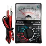
For flexible settings, I recommend connecting a variable resistor, rotating its shaft to achieve the desired tone of sound, then measure its resistance with an ohmmeter, twisting nothing, and replace it with the closest nominal resistor available. If you find a capacitor, you can turn on the trimmer, but some may have problems measuring its capacitance - not all multimeters are capable.

Particular attention is paid to the keys. Standard tact buttons are too rigid, requiring relatively significant force to close their internal contacts. I recommend using them only with a certain lever, similar to a piano key. I found buttons that require extremely little effort to press and also have a long cylinder for pressure.

By listening to the output signal for a short time with a change in the angle of rotation of the rotor of the variable resistor, in my opinion, quite good sound frequencies for each key were chosen. Below is a table of the frequency and resistance of a resistor suitable for this purpose.

If you wish, you can easily calculate the ratings of radio components for the frequency you are interested in, in those. documentation indicates the maximum operating frequency of the timer is 200 kHz. The human ear hears oscillations with a frequency of 20 Hz - 20 kilohertz, so the possibilities of this electronic component are even more than we need. I will briefly show how it is calculated. The first resistor was chosen at 4.7 kOhm - 4700 Ohm. From the basic formula taken from the technical documentation 555, it is easy to derive the resistance R2 for given R1, C1 and the chosen frequency itself.

The entire board, thanks to surface-mount components, is extremely small. Any NPN transistor, you can use BC847, the location of its BEC is standard, the same as for all bipolar transistors in the SOT-23 package. Power supply 5-18 V, but even works from one lithium-ion cell.

It is also possible to insert such a circuit into an old non-working children's melodic synthesizer. It is better to throw the fifth output of the “Control” microcircuit to minus through an output capacitor with a capacity of about 100 nF.
When a low-resistance speaker is connected, the transistor heats up noticeably, this can and should be prevented by increasing the value of its base resistor or turning on a high-resistance speaker from an old phone. In my copy, it turned out that the buttons with resistors were located on one board, and the microcircuit on the second: connected them with tinned tin plates. It is better to fasten the buttons not only with contacts using solder contacts, but also fill this case with hot glue or epoxy, when the values \u200b\u200bfor the desired sound are already precisely selected.
Related Articles