How to connect an electromagnetic starter. Magnetic starter connection diagram, electrician's notes
A magnetic starter is an electrical device that is designed to start at a distance, assist in operation, turn off and save an electric motor. It is easy to assemble a diagram for connecting a magnetic starter via a push-button post. The operation of an MF is based on the effect of the appearance of a magnetic field when current penetrates through an induction load, that is, through a coil.
What is MP used for?
Starters are often used to mechanically turn on heaters, lighting lines, etc. They are also used to operate engines. MP connection diagrams differ mainly depending on which coil is located in it. It is not difficult to turn on the starter yourself, but you can make it easier and purchase the starter already assembled, preferably with a plastic case.
In it, the structure is already assembled and the control buttons on the lid are connected. You only need to connect the electrical cables at the top and the outlet wire to the load.
MP coil
The coil is the main part of the MP; it creates an electromagnetic field when electricity passes through it, and involves an armature, 3 or 5 pairs of mobile contacts. The type of coil depends on the voltage in the installation. They can operate from 220 volts or are designed for 380 volts. The coil, with a calculated 220 volts, is connected to the terminals between ground and phase. 380 volts are connected between phases.
The voltage value is usually written on its terminal next to the bolt with which the wire is clamped. If you turn on a 220-volt coil like a 380-volt coil, it will explode.
Preparing for assembly
Before directly assembling the circuit for connection, you need:

Types of starter designs
For the reversible design of the MP, the first, third and fifth terminals are connected with the same numbers of the adjacent device. And the outgoing wires are connected crosswise: the second to the sixth, the fourth to the fourth, the sixth to the second. The wire that powers the electric motor is connected to the second, fourth and sixth terminals of any starter.
The cross connection circuit prohibits the simultaneous operation of two devices, as this will lead to a short circuit.
Because of this, it is necessary that the conductor of the circuit block of both starters pass first through the closed contactor of the other, and then through the open contact of its own. Then when you turn on the first device, the second device will turn off and vice versa.
Some MP designs require only 5 pairs of contactors that close. Then the wire of the circuit block of the 1st MP is connected to the closed “Start” contacts of the other. This design operates in a start-stop manner.
3 wires are connected to the second terminal of the “Stop” button: 2 blocks and one that powers the “Start” button; these wires are connected in parallel to each other. With this design, “Stop” turns off any device and stops the operation of the electric motor.
All work on installation and repair of MP structures is done after the voltage has been removed, even if the control switches the neutral.
MP connection diagram
A popular scheme for connecting a magnetic starter via a push-button post.
The main circuit has two parts:
- Three pairs of power contacts direct electrical power to electrical equipment.
- A graphical representation of the control, which consists of a coil, buttons and additional contactors that take part in the operation of the coil or prevent erroneous activation.
Our readers recommend! To save on electricity bills, our readers recommend the ‘Electricity Saving Box’. Monthly payments will be 30-50% less than they were before using the saver. It removes the reactive component from the network, resulting in a reduction in load and, as a consequence, current consumption. Electrical appliances consume less electricity and costs are reduced.
The most common wiring diagram is with one device. It's the easiest thing to deal with. To connect its main parts, you need to take a three-core cable and a pair of open contactors when the device is turned off.
Scheme with connecting a 220 volt coil
Will analyze a design with a voltage of 220 volts. If the voltage is 380 volts, you need to connect a different type of phase instead of the blue zero. In this situation, black or red. In case of blocking of the contactor, the fourth pair is taken, which works with 3 power pairs. They are located at the top, but the side ones are located on the side.
 Pairs of power contactors are supplied with 3 phases A, B and C from the machine. To turn on when you touch the “Start” button, it is necessary that the voltage be equal to 220 V on the core, which will help the movable contactors connect with those that are stationary. The circuit will begin to close; to disconnect it, you need to disconnect the coil.
To assemble the control circuit, you need to connect one phase directly to the core, and connect the second phase using a wire to the start contact.
From the 2nd contactor we lay 1 more wire through the contacts to the other open contact of the “Start” button. A blue jumper is also made from it for the closed contactor of the “Stop” button; a zero from the electrical supply is connected to the 2nd contactor.
Working principle
The operating principle is simple. If you press the “Start” button, its contacts begin to close and a voltage of 220 volts flows to the core - it triggers the main and side contacts and an electromagnetic flux occurs. If the button is released, the contactors of the start button open, but the device is still turned on, since zero is transmitted to the coil through the closed blocking contacts.
In order to turn off the MP, you need to break the zero by opening the contacts of the “Stop” button. Again the device will not turn on, because the zero will be broken. To turn it on again, you will need to click “Start”.
How to connect a thermal relay?

You can also make a single-line graphic drawing of the connection of a three-phase electric motor to a magnetic starter via a relay.
Between the MP and an asynchronous electric motor, a relay is connected in series, which is selected depending on the specific type of motor. This device protects the motor from breakdowns and emergency conditions (for example, when one of the three phases disappears).
The relay is connected to the output from the MP to the electric motor, electricity passes through it in a series manner through the heating of the relay to the electric motor. On top of the relay there are additional contactors, which are combined with the coil.
Relay operation
Thermal relay heaters are designed for the maximum current that passes through them. When the current rises to unsafe limits for the motor, the heaters turn off the MP.
Installation of starters inside an electrical panel
The design of the MP allows installation in the middle of the electrical panel. But there are rules that apply to all devices. To ensure high reliability of operation, it is necessary that the installation be made on an almost straight and solid plane. Moreover, it is located vertically on the wall of the electrical panel. If there is a thermal relay in the design, then it is necessary that the temperature difference between the MP and the electric motor be as small as possible.
In what places should you not install MP?
To prevent accidental activation of the starter or to protect it, do not install the device in places that are susceptible to shocks, shocks, or shaking.
It is also impossible to install the MP in the same room with devices that have a current higher than 150 A. When these devices are turned on and off, a quick shock occurs.
The wires in the wiring diagram also need to be routed correctly. In order for there to be good contact and no bending of the spring clamp washers, it is necessary to bend them in a round shape.
The design of the device is made after removing the voltage. The cores can operate from 220 volts or 380 volts. You can also buy a ready-made MP, this will greatly simplify the situation.
Magnetic starters are electromechanical devices designed to simultaneously connect an electrical energy consumer to three supply phases. Its action is based on the effect of the appearance of a magnetic field when an electric current passes through an inductive load (retractor coil). They are used, as a rule, to control three-phase electric motors, and also, for example, in emergency transfer systems.
The main difference in the connection and control schemes of a magnetic starter is what type of retractor coil is used in it.
The retractor coil of a magnetic starter is its “heart,” which initiates a magnetic field when electric current passes through it and retracts an armature with three (sometimes five) pairs of movable contacts. The type of coil depends on the magnitude of the actuation voltage. They are:
- Operated by voltage 220 V.
- Designed for voltage 380 V.
The 220 V coil terminals are connected between phase and neutral (ground). Three hundred eighty volts - between phases. The operating voltage of the coil is usually written on its dielectric terminal next to the wire clamp bolt.
Two hundred and twenty volt coils explode spectacularly when switched between phases.
How to properly connect a magnetic starter
When the armature of the magnetic starter is pulled into the hole of the electromagnetic coil, two actions occur:
- Pairs of movable contacts on the armature are closed with fixed ones on the starter body, due to which the supply voltage is switched and the consumer (electric motor) is connected.
- Groups of control contacts are activated (they can be closed or opened), to which the “Start” and “Stop” buttons are connected, as well as the controlled terminal of the electromagnetic coil.
When installing a magnetic starter, one phase from its supply terminal (on the power line side) is supplied to any terminal of the retractor coil. This connection is permanent. The second terminal of the electromagnetic coil is connected to the control circuit.
 Three-phase motors are often used at home. To properly connect such a device, you need to know its characteristics, advantages and disadvantages, as well as.
To install high-power devices in a single-phase network, just read the following.
If the coil is designed to operate from 220 V, then the control circuit switches the neutral. If the operating voltage of the electromagnetic coil is 380 V, then the current flows in the control circuit, “removed” from the other supply terminal of the starter.
The type of control circuit depends on whether you intend to reverse the engine or not.
Control circuit without motor reversing
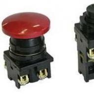
If it is not necessary to change the direction of rotation of the engine, then the control circuit uses two non-fixed spring-loaded buttons: one in the normal position is open - “Start”, the other is closed - “Stop”. As a rule, they are manufactured in a single dielectric housing, and one of them is red. 
Such buttons usually have two pairs of contact groups - one normally open, the other closed. Their type is determined during installation work visually or using a testing device (tester) turned on in audible alarm mode.
 Thanks to dimmers, you can not only save on lighting, but also create an interesting lighting design for your apartment or house. Taking into account the operating network voltage, the optimal one is selected based on its characteristics.
Motion sensors are used to organize home lighting. You can read how to choose them, and the features of its connection diagram are revealed.
The control circuit wire is connected to the first terminal of the closed contacts of the Stop button. Two wires are connected to the second terminal of this button: one goes to any of the closest open contacts of the “Start” button, the second is connected to the control contact on the magnetic starter, which is open when the coil is turned off. This open contact is connected by a short wire to the controlled terminal of the coil.
The second wire from the “Start” button is connected directly to the terminal of the retractor coil. Thus, two wires must be connected to the controlled “pull-in” terminal – “direct” and “blocking”.
The principle of operation of a magnetic starter in such a circuit is as follows: when the “Start” button is closed, the terminal of the retractor coil is connected to the phase or neutral, which causes the magnetic starter to operate. In this case, pairs of movable contacts on the armature are closed with fixed ones and voltage is supplied to the motor.At the same time, the control contact closes and, thanks to the closed “Stop” button, the control action on the retractor coil is fixed. When the Start button is released, the magnetic starter remains closed. Opening the contacts of the “Stop” button causes the electromagnetic coil to be disconnected from the phase or neutral and the electric motor is turned off.
Connection diagram for reversing magnetic starter
Before connecting a reversing magnetic starter, you need to understand the components of the proposed circuit.
To reverse the motor, two magnetic starters and three control buttons are required. Magnetic starters are installed next to each other. For greater clarity, let’s conditionally mark their supply terminals as 1–3–5, and those to which the motor is connected as 2–4–6. 
For a reversible control circuit, the starters are connected as follows: terminals 1, 3 and 5 with the corresponding numbers of the adjacent starter. And the “output” contacts are crosswise: 2 from 6, 4 from 4, 6 from 2. The wire feeding the electric motor is connected to three terminals 2, 4, 6 of any starter.
With a cross connection scheme, simultaneous operation of both starters will result in a short circuit. Therefore, the conductor of the “blocking” circuit of each starter must first pass through the closed control contact of the adjacent one, and then through the open one of its own. Then turning on the second starter will cause the first one to turn off and vice versa.
Some magnetic starter designs have only five pairs of contacts that can be closed. In this case, the wire of the blocking circuit of one starter is connected to the permanently closed contacts of the “Start” button of the other. As a result, it begins to work in “start-stop” mode.Not two, but three wires are connected to the second terminal of the closed “Stop” button: two “blocking” and one supplying the “Start” button, connected in parallel to each other. With this connection scheme, the “Stop” button turns off any of the connected starters and stops the electric motor.
All installation and repair work in the wiring diagrams for connecting a magnetic starter are carried out with the voltage removed, even if the control circuit switches the neutral.
An example of using a reversing magnetic starter - connection diagram on video
To supply power to motors or any other devices, contactors or magnetic starters are used. Devices designed to be powered on and off frequently. The connection diagram for a magnetic starter for a single-phase and three-phase network will be discussed further.
Contactors and starters - what's the difference?
Both contactors and starters are designed to close/open contacts in electrical circuits, usually power ones. Both devices are assembled on the basis of an electromagnet and can operate in DC and AC circuits of different powers - from 10 V to 440 V DC and up to 600 V AC. Have:
- a certain number of working (power) contacts through which voltage is supplied to the connected load;
- a number of auxiliary contacts - for organizing signal circuits.
So what's the difference? What is the difference between contactors and starters? First of all, they differ in the degree of protection. Contactors have powerful arc extinguishing chambers. This leads to two other differences: due to the presence of arc arresters, contactors are large in size and weight, and are also used in circuits with high currents. For low currents - up to 10 A - only starters are produced. By the way, they are not produced for high currents.
There is one more design feature: the starters are produced in a plastic case, with only the contact pads exposed outside. Contactors, in most cases, do not have a housing, therefore they must be installed in protective housings or boxes that will protect against accidental contact with live parts, as well as from rain and dust.
In addition, there is some difference in purpose. The starters are designed to start asynchronous three-phase motors. Therefore, they have three pairs of power contacts - for connecting three phases, and one auxiliary one, through which power continues to flow to operate the engine after the “start” button is released. But since a similar operating algorithm is suitable for many devices, a wide variety of devices are connected through them - lighting circuits, various devices and instruments.
Apparently because the “filling” and functions of both devices are almost the same, in many price lists the starters are called “small contactors”.
Design and principle of operation
To better understand the connection diagrams of a magnetic starter, you need to understand its structure and operating principle.
The base of the starter is a magnetic circuit and an inductor. The magnetic core consists of two parts - movable and stationary. They are made in the form of the letters “Ш” with their “legs” facing each other.
The lower part is fixed to the body and is stationary, the upper part is spring-loaded and can move freely. A coil is installed in the slot in the lower part of the magnetic circuit. Depending on how the coil is wound, the rating of the contactor changes. There are coils for 12 V, 24 V, 110 V, 220 V and 380 V. On the top of the magnetic circuit there are two groups of contacts - movable and fixed.

In the absence of power, the springs press out the upper part of the magnetic circuit, the contacts are in their original state. When voltage appears (press the start button, for example), the coil generates an electromagnetic field that attracts the upper part of the core. In this case, the contacts change their position (picture on the right).
When the voltage drops, the electromagnetic field also disappears, the springs push the moving part of the magnetic circuit up, and the contacts return to their original state. This is the principle of operation of an electromagnetic starter: when voltage is applied, the contacts close, and when voltage is lost, they open. Any voltage can be applied to the contacts and connected to them - either constant or alternating. It is important that its parameters are not greater than those declared by the manufacturer.

There is one more nuance: the starter contacts can be of two types: normally closed and normally open. Their operating principle is clear from the names. Normally closed contacts are switched off when triggered, while normally open contacts are closed. The second type is used to supply power; it is the most common.
Connection diagrams for a magnetic starter with a 220 V coil
Before we move on to the diagrams, let’s figure out what and how these devices can be connected. Most often, two buttons are required - “start” and “stop”. They can be made in separate housings, or they can be a single housing. This is the so-called push-button post.

Everything is clear with individual buttons - they have two contacts. One receives power, the other leaves it. There are two groups of contacts in the post - two for each button: two for start, two for stop, each group on its own side. There is also usually a ground terminal. Nothing complicated either.
Connecting a starter with a 220 V coil to the network
Actually, there are many options for connecting contactors; we will describe a few. The diagram for connecting a magnetic starter to a single-phase network is simpler, so let's start with it - it will be easier to understand further.
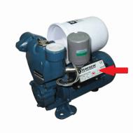
Power, in this case 220 V, is supplied to the coil terminals, which are designated A1 and A2. Both of these contacts are located at the top of the case (see photo).

If you connect a cord with a plug to these contacts (as in the photo), the device will be in operation after the plug is inserted into the socket. In this case, any voltage can be applied to the power contacts L1, L2, L3, and it can be removed when the starter is triggered from contacts T1, T2 and T3, respectively. For example, a constant voltage from a battery can be supplied to the inputs L1 and L2, which will power some device that will need to be connected to the outputs T1 and T2.

When connecting single-phase power to the coil, it does not matter which output is supplied with zero and which with phase. You can switch the wires. Even most often, the phase is supplied to A2, since for convenience this contact is located on the bottom side of the housing. And in some cases it is more convenient to use it and connect the “zero” to A1.
But, as you understand, this scheme for connecting a magnetic starter is not particularly convenient - you can also supply conductors directly from the power source by building in a regular switch. But there are much more interesting options. For example, you can supply power to the coil through a time relay or light sensor, and connect a power line to the contacts. In this case, the phase is connected to contact L1, and zero can be taken by connecting to the corresponding coil output connector (in the photo above it is A2).
Diagram with start and stop buttons
Magnetic starters are most often installed to turn on an electric motor. It is more convenient to work in this mode if there are “start” and “stop” buttons. They are connected in series to the phase supply circuit to the output of the magnetic coil. In this case, the diagram looks like the figure below. note that

But with this method of switching on, the starter will operate only as long as the “start” button is held down, and this is not what is required for long-term operation of the engine. Therefore, a so-called self-catching circuit is added to the circuit. It is implemented using auxiliary contacts on the starter NO 13 and NO 14, which are connected in parallel with the start button.

In this case, after the START button returns to its original state, power continues to flow through these closed contacts, since the magnet has already been attracted. And power is supplied until the circuit is broken by pressing the “stop” key or by triggering a thermal relay, if there is one in the circuit.
Power for the motor or any other load (phase from 220 V) is supplied to any of the contacts marked with the letter L, and is removed from the contact marked T located underneath it.
It is shown in detail in what order it is better to connect the wires in the following video. The whole difference is that not two separate buttons are used, but a push-button post or push-button station. Instead of a voltmeter, you can connect a motor, pump, lighting, or any device that operates on a 220 V network.
Connecting a 380 V asynchronous motor via a starter with a 220 V coil
This circuit differs only in that three phases are connected to contacts L1, L2, L3 and three phases also go to the load. One of the phases is energized to the starter coil - contacts A1 or A2. In the figure this is phase B, but most often it is phase C as it is less loaded. The second contact is connected to the neutral wire. A jumper is also installed to maintain power supply to the coil after the START button is released.

As you can see, the scheme has remained virtually unchanged. Only it added a thermal relay that will protect the engine from overheating. The assembly procedure is in the next video. Only the assembly of the contact group differs - all three phases are connected.
Reversible circuit for connecting an electric motor through starters
In some cases, it is necessary to ensure that the motor rotates in both directions. For example, for the operation of a winch, in some other cases. A change in the direction of rotation occurs due to phase reversal - when connecting one of the starters, two phases must be swapped (for example, phases B and C). The circuit consists of two identical starters and a button block, which includes a common “Stop” button and two “Back” and “Forward” buttons.

To increase safety, a thermal relay has been added, through which two phases pass, the third is supplied directly, since protection in two is more than enough.
Starters can be with a 380 V or 220 V coil (indicated in the specifications on the cover). If it is 220 V, one of the phases (any) is supplied to the coil contacts, and “zero” from the panel is supplied to the second. If the coil is 380 V, any two phases are supplied to it.
Also note that the wire from the power button (right or left) is not fed directly to the coil, but through the permanently closed contacts of another starter. Contacts KM1 and KM2 are shown next to the starter coil. This creates an electrical interlock that prevents two contactors from being energized at the same time.

Since not all starters have normally closed contacts, you can take them by installing an additional block with contacts, which is also called a contact attachment. This attachment snaps into special holders; its contact groups work together with the groups of the main body.
The following video shows a diagram of connecting a magnetic starter with reverse on an old stand using old equipment, but the general procedure is clear.
For those who had a normal attitude towards studying a school physics course, it will not be difficult to understand the connection diagrams of various electrical equipment, including three-phase electric motors. They are connected via contactors or magnetic starters. Foreign classification does not make any difference between these devices, since the starter is the same contactor, but equipped with additional devices for the safe operation of the current consumer.
In other words, a starter is a kind of miniature electrical cabinet, in which, in addition to the contactor, thermal protection and short circuit protection are installed. The starters have 8 values from “0” to “7”, each of which is designed for electric motors with a certain power range (rated current). Thanks to the closed design (in the housing), the starters can be installed anywhere. When connecting electric motors via a contactor, protective devices are selected separately.
Contact system on the contactor
Regardless of the standard size and manufacturer of electrical equipment, any three-phase contactor has a standard diagram of contacts and their connections. For ease of installation, all contacts are marked indicating their purpose. The marking is applied to the body of the device and looks like this:
- A1 (zero) and A2 (phase) – contacts for controlling the switching on and off of the contactor;
- Odd numbers 1, 3, 5 and markings L1, L2, L3 indicate the three-phase power input locations;
- Even numbers 2, 4, 6 and markings T1, T2, T3 indicate the connection points of the wires going to the current consumer;
- 13NO and 14NO are a pair of block contacts to provide the self-latching function.
Contact A2 is duplicated in the upper and lower parts of the device body for ease of switching. For the same purpose, the upper and lower (odd and even) group of power contacts can also be used to input or output power. When installing the contactor, you must be careful, otherwise the circuit will not work.
Incorrect phase connections must not be allowed. If you mix them up when installing the contactor, you will get reverse rotation of the motor. For this purpose, there are two ways of marking the insulation of cable cores - with numbers and color. The colors 1, 2 and 3 are yellow, green and red. The neutral conductor is white or marked with the number “0”. Connecting power contacts is not difficult. The main thing is the correct connection of the control voltage through the push-button station.
Connecting a push-button station


Let's consider 2 diagrams for connecting a contactor to a 380 V network: for a coil with a supply voltage of 380 V and 220 V.
The push-button post has two buttons. “Start” with normally open and “Stop” with normally closed contacts. Power is supplied to it (phase) through contact No. 4 of the “Stop” button. We install a jumper between terminals No. 3 “Stop” and No. 2 “Start,” thereby extending the “phase” line. Terminal A1 (phase) of the contactor is connected to contact No. 1 “Start”. The neutral conductor of the control wire is connected to terminal A2. A jumper is installed between the double contact A1 and terminal 14NO. Terminal 13NO is connected to contact No. 2 “Start”.

If the control circuit needs to be powered from one phase (phase-zero), with a starter coil rating of 220 V, the connection diagram will look like this.

When you press the “Start” button, the power contacts are activated and voltage is supplied to the block contact, which ensures the working (closed) position of the power contacts after the button is released. By pressing the “Stop” button, the circuit on the block contact is broken, and the power contacts move to the normally open position. More detailed descriptions of connecting contactors with illustrations and videos can be found on the Internet. Having done this work several times, in the future you will perform it automatically.
The connection diagram for a magnetic starter seems complicated at first glance, but dealing with such a device will not be difficult if you follow the installation rules and recommendations.
At its core, a magnetic starter (push-button or contactless) is a device that can be classified as a type of electromagnetic contact that allows it to cope with current loads.
It works during constant switching on and off of circuits.
With the connection of a magnetic starter, it becomes possible to remotely control the start, stop and general operation of a three-phase electric motor.
However, such a relay is so unpretentious that it allows you to control other mechanisms: lighting, compressors, pumps, taps, a thermal heater or furnace, and air conditioners.
When buying such a mechanism, pay attention: after all, a push-button magnetic starter is not much different from a modern contactor.
Their functions are almost identical, so there should not be any special difficulties when connecting.
The principle of operation of the circuit is quite simple. Voltage is applied to the starter coil, after which a magnetic field appears in it.
It is due to this that the metal core is drawn into the coil.
We attach power contacts to the core, which close when activated, allowing current to flow freely through the wires.
The magnetic starter circuit contains a post where buttons are installed that activate the starting and stopping mechanisms.
How does the starter mechanism work?
Before connecting a magnetic starter, you need to understand its configuration diagram: it includes the device itself and a post (block) with the most important contacts.

Although it is not included in the main part of the relay circuit, when working in a circuit with additional wire elements, for example, with a motor reverser, it is necessary to provide branching of the wires.
This is where a block is needed, which is also called a contact-type attachment to the circuit.
Inside such a set-top box there is a contact circuit connected, which is tightly connected to the conventional contact system of a magnetic starter.
Such a mechanism for a three-phase motor, for example, consists of two pairs of closed and two pairs of open contacts.
To remove the blocking component (during repair or connection), it is enough to move away the special slides holding the cover.
The diagram consists of two parts: upper and lower. The push-button mechanism for a three-phase motor is easy to distinguish by color. For example, the Stop button is red.
It has a break contact connected through which voltage will pass into the circuit. The button that will be responsible for launching is colored green.
It uses a normally open contact that, when connected, conducts electrical current through the circuit.
The connection diagram for a reversing magnetic starter is usually protected against accidental pressing.
To do this, additional side contacts are installed, where when one is triggered, the second will be blocked.
The wiring diagram is performed in a couple of steps, but in practice it turns out to be a convenient push-button mechanism.
Device connection diagram
Before the magnetic starter circuit is connected, you must:
- Ensure de-energization on the entire front of our work (de-energization of the engine, parts of the wiring). You can check the absence of voltage using special indicator tools, the simplest of which is a screwdriver, sold in any hardware store;
- Find out the operating voltage, this is especially true for the coil element. It is written not on the starter packaging itself, but directly on the device. There are only two options: 380v or 220 volts. When we choose 220 volts and not 380v, then when connecting a photo relay, phase and zero are supplied to the coil. If we are talking about 380V, and not 229, then we use two opposite phases. If you do not understand between 220 and 380 volt relays, then the circuit may simply burn out from the voltage difference;
- We select the appropriate buttons of the corresponding colors;
- For a relay, all zeros, which are incoming and outgoing, as well as elements that make it possible to achieve grounding, are connected in the circuit on the terminal block through the device without touching it. For a 220 volt coil, zero is taken during connection, which should not be done for 380 volts.
The connection sequence consists of the following parts:
- three pairs of power elements that will be responsible for supplying power, be it an electric motor circuit or any device;
- control circuit, including a coil, additional wires and buttons.
The simplest process is considered to be connecting a reversing magnetic starter in the amount of one unit. This is the simplest circuit (220 or 380 volts), most often it is used in engine operation.

For a photo relay we need a three-wire wire, which we will connect to the buttons, as well as a pair of open contacts.
Consider a typical 220 volt connection diagram. If you have chosen a 380 volt connection scheme, then instead of the blue zero it is important to connect another phase of different names.
The photo relay contact post is the fourth free phase. Three phases go to the power contacts through the circuit.
So that they can be connected normally, we supply 220 volts to the coil (or 380, depending on the choice of relay). The circuit will close and we will be able to control the operation of the electric motor.
Connecting the thermal relay
A thermal relay can be placed between the magnetic starter and the motor device, which may be needed to safely supply current to the motor device.
Why do you need to connect a thermal relay? It doesn’t matter what voltage is in our circuit, 220 or 380 volts: during surges, any motor can burn out. That is why it is worth setting up a post for protection.
The photo relay allows the circuit to operate even if one of the phases has burned out.

Connect a photo relay at the output of the magnetic starter to the motor device. Then a current of 220 or 380 volts passes through the post from the photorelay heater and gets inside the engine.
On the photo relay itself you can find contacts that should be connected to the coil.
Thermal relay heaters (photo relays) do not last forever and have their own operating limits.
Thus, the post of such a magnetic starter will be able to pass through itself only a certain current indicator, which may have a maximum limit.
Otherwise, the consequences of the photo relay operation for the engine will be disastrous - despite the protective post, it will burn out.

If an unpleasant situation arises when a current above the specified limits is passed through the post, then the heaters begin to act on the contacts, disrupting the general circuit in the device.
As a result, the starter turns off.
When choosing a photo relay for a motor, pay attention to its characteristics. The current of the mechanism must be suitable for the engine power (designed for 220 or 380 volts).
It is not recommended to install such a protective post on ordinary devices - only on motors.
How to choose the right magnetic starter?
To prevent the device from burning out after connecting it after a couple of weeks, you need to be careful about your choice. The most popular starter series are PML and PM12.
They are supplied by both domestic and foreign companies.

Each digit of the value indicates the current that the post can conduct through the circuit without breakdowns or fires. If the load current is higher than 63 A, then it is better to buy contactors to connect to the circuit.
An important characteristic when connecting is the wear resistance class. It shows how many times the device can be pressed without difficulty.
An important indicator if the mechanism has to be turned on and off frequently. If there are a lot of clicks per hour, then contactless starters are chosen.
In addition, devices can be sold with or without reverses. Used for reversible engines, where rotation occurs in two directions at once.
A starter of this type has two coils and two pairs of power contacts. Additional elements include a security mechanism, a light bulb, and buttons.
Articles on the topic