Scheme and do-it-yourself manufacturing of a stroboscope for an ignition installation (UOZ). How to assemble a stroboscope for installing the ignition with your own hands? DIY LED strobe lights
Owners of carbureted cars are familiar with the difficulties of the ignition adjustment process. Usually this is done by ear, which is not very convenient. Using a stroboscope, this process can be facilitated. However, industrial devices are quite expensive, so many make a strobe for ignition with their own hands.
Disadvantages of industrial models
Industrial devices often have certain disadvantages, due to which the usefulness of the device is very doubtful.
For starters, they are quite pricey. For example, modern digital models will cost a motorist 1000 rubles. More functional models already cost from 1700. Advanced stroboscopes cost about 5500 rubles. Needless to say, a car stroboscope (made with your own hands) will cost a motorist 100-200 rubles.
Often in factory devices, the manufacturer uses a particularly expensive discharge lamp. The lamp has a certain resource, and after a while it will have to be replaced. And this in itself is tantamount to acquiring a new factory device.
Why is it worth making a stroboscope with your own hands?
The disadvantages of factory and technological devices are pushing the motorist to independently manufacture this device. In addition, it is much cheaper to equip this equipment with LEDs instead of an expensive lamp. An ordinary laser pointer or flashlight is suitable as a source of diodes or a donor.
The rest of the details will also cost a penny. It does not require any special tools. The budget for the manufacturing process of a stroboscope will be no more than 100 rubles.
How to make a stroboscope with your own hands?
There are a huge number of schemes and options for manufacturing. However, for the most part, all projects to create this gadget are similar. Let's see what is needed for assembly.

We need a simple transistor KT315. It can be easily found in an old Soviet receiver. The designation may be slightly different, but it does not matter. The thyristor KU112A can be easily obtained from the power supply of an old TV. You can also find small resistors there. Since we make an LED strobe with our own hands, then, of course, we need an LED flashlight. To do this, it is better to purchase the cheapest one from China. In addition, you need to stock up on a capacitor up to 16 V with any low-frequency diode, a small 12 A relay, wires, crocodiles, a shielded wire 0.5 m long, and a small piece of copper wire.
We assemble the device
The scheme is small, and you can place it right in the same Chinese lantern. So, through the hole in the flashlight at the back, it is desirable to pass the wires to power the device. At the ends of the wires, it is better to solder crocodiles. A hole needs to be made in the side wall, if the Chinese have not already made it. A shielded wire will be routed through this hole. At the opposite end, it is necessary to insulate the braid and solder the same piece of copper wire to the main core of the wire. This will be the sensor.
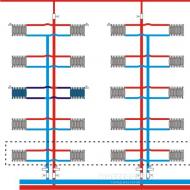
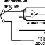
Device diagram and principle of operation
After applying current through the power wires, the capacitor will charge very quickly through the resistor. When a certain charge threshold is reached, the voltage will flow through the resistor to the opening contact of the transistor. This is where the relay comes in. When the relay closes, it will create a circuit of thyristor, LED and capacitor. Then, through the divider, the pulse will go to the control output of the thyristor. Next, the thyristor will open, and the capacitor will be discharged to the LEDs. As a result, a do-it-yourself stroboscope will flash brightly.

Through a resistor and a thyristor, the base output of the transistor is connected to a common wire. Because of this, the transistor will close, and the relay will turn off. The time of the glow of the LEDs increases, since the contact is not broken immediately. But the contact will break, and the thyristor will be de-energized. The circuit will return to its base position until a new pulse arrives.
By changing the capacitance of the capacitor, you can change the glow time. If you choose a capacitor with a larger capacity, then the LED stroboscope, made by yourself, will glow brighter and last longer.
device on a microcircuit
The main part of this simple circuit is a DD1 chip. This is the so-called single vibrator 155AG1. In this circuit, it starts only from negative pulses. The control signal will go to the KT315 transistor, and it will generate these negative pulses. Resistors 150 K ohm, 1 k ohm, 10 k ohm, as well as the KS139 zener diode work as limiters for the amplitude of the incoming signal from the ignition of the car.
A 0.1 mF capacitor together with a 20 kΩ resistance will set the desired pulse duration that will be generated by the microcircuit. With such a capacitance of the capacitor, the duration of the pulses will be up to about 2 ms.
Then, from the 6th leg of the microcircuit, the pulses, which by this moment will be synchronized with the ignition of the car, will go to the base output of the KT 829 transistor. It is here as a key. The result is a pulsed current through the LEDs.

How is this auto strobe powered? With our own hands, we need to run a couple of wires to the terminals of the car battery. It is necessary to monitor the level of battery charge.
If you correctly assemble this simple circuit, you will immediately be able to see how the device works. If suddenly the brightness is not enough, then this is regulated by the selection of the appropriate resistance.
As a housing for the device, you can use an old or Chinese flashlight.
Another stroboscope circuit
This do-it-yourself LED stroboscope, made according to this principle, can also be powered from a car battery. Diodes will provide protection against reverse polarity. As a fastener, an ordinary crocodile is used here. It must be attached to the high voltage contact of the first spark plug on the motor. Next, the pulse will pass through the resistors and the capacitor and come to the input of the trigger. By that time, this input will already be turned on by the one-shot.
Before the pulse, the one-shot is in normal mode. The direct trigger output is low. Inverted input, respectively - high. A capacitor connected with a plus to the inverted output will be charged through a resistor.
A high-level pulse fires a one-shot, which switches the flip-flop and serves to charge the capacitor through the resistor. After 15 ms, the capacitor will be fully charged and the trigger will switch to normal mode.
As a result, the one-shot will respond to this with a synchronous sequence of rectangular pulses with a duration of approximately 15 ms. The duration can be adjusted by changing the resistor and capacitor.

The pulses of the second microcircuit are up to 1.5 ms. For this period, transistors open, which are an electronic switch. Then current flows through the LEDs. According to this principle, a strobe for a car works (it was made by hand or not, it does not matter - both devices shine the same way).
The current passing through the LEDs is much greater than the passport one. But, since the flashes are short, the LEDs will not fail. The brightness will be enough to use this useful device even in the daytime.

This do-it-yourself stroboscope can be assembled in a case from the same long-suffering pocket flashlight.
How to work with the device?
Having assembled the device according to one of the above schemes, you can simply and easily, and most importantly, accurately adjust the ignition on carburetor engines, check the correct operation of candles and coils, and control the operation of the advance angle regulators.
In order to set the ignition as correctly as possible, it is usually assumed that the mixture ignites a couple of degrees before the piston reaches its highest point. This angle is called the "advance angle". As the crankshaft rpm increases, the angle should also increase. So, this angle is set at idle, and then it is necessary to check the correctness of the settings in all operating modes of the unit.
We set the ignition
We start and warm up the engine. Now we power our LED stroboscope and connect the sensor. Now you need to point the device at the mark on the timing case and find the mark on the flywheel. If the moment is violated, then the marks will be far enough apart. By rotating the timing case, match the marks. When you have found this position, fix the distributor.

Then it's time to pick up the pace. The labels will diverge, but this is a completely normal situation. This is how the ignition is adjusted using a stroboscope.
So, we found out how a do-it-yourself LED stroboscope is made.
To accurately set the ignition on the engine, it is necessary to use special devices - stroboscopes. They can be purchased at car dealerships or made by hand. In the second case, you will save a decent amount and make the most suitable device for your car model.
Features of factory strobe lights and the principle of their operation
Precisely adjusting the ignition without using a strobe is quite difficult. Such a device significantly speeds up the tuning process, the lamp signals the appearance of a spark, which allows you to correctly set the ignition timing. Despite the fact that factory instruments work efficiently and accurately, many motorists are in no hurry to buy them. The main deterrent can be called the high price of strobe lights. Most models use an expensive gas discharge lamp, replacing it is equivalent to buying a new device.
The device itself can be made by hand, using simple and affordable materials. There are several good manufacturing schemes that will help you save on buying factory counterparts. For example, you can see the prices for the most popular strobe lights that are on sale:
- Multitronics C2 - 900-1000 rubles.
- AstroL5 - 1300 rubles.
- Focus F1 - 1700 rubles.
- Focus F10 - 5600 rub.
Homemade devices are made from flashlights, LEDs or a laser pointer. At a low cost (about 500 rubles), the device will work no less reliably and efficiently.
Instructions for the manufacture of the device for installing the ignition
The easy way
There are many different schemes on the network, almost all of them are easy to assemble and do not require large expenditures on materials. Consider one of the most popular schemes for creating a stroboscope at home. From the details we need:
- transistor KT315;
- thyristor KU112A, 0.125 W resistors;
- any flashlight on diodes (diodes should be 6 or more);
- capacitors C1;
- low frequency diode V2;
- relay with index RWH-SH-112D;
- 1 meter power cord;
- special clamps;
- copper wire about 10 cm.
All parts can be purchased at the radio market or in a specialized store. As a housing for the device, you can use an old flashlight or a flash from a camera.

Assembly diagram of a car strobe in a housing from an old flashlight

You can use such a device not only to install the ignition. They can check the candle, adjust the operation of the regulator.
Homemade stray using a timer
A stroboscope based on timer devices has a more complex circuit. Its main advantage is stable light pulses that do not depend on battery voltage. The device can also work in tachometer mode, for this you just need to change the position of the regulator.

Timed strobe lights can also be used as a tachometer
Tip: It is better to use diodes from the KD521 series in the circuit. If you have not found a domestic-made timer, you can take a foreign analogue NE555.
Scheme for manufacturing a device on LEDs
Such a device is based on the 155AG1 chip; it is triggered by pulses with negative polarity. The circuit uses resistances R1, R2, R3, which limit the amplitude of the input signal. The required pulse duration is set by capacitance C4 and resistor R6. At default settings, this is 2 ms. The vehicle battery will be used as a power source.

LED strobe lights are highly reliable and can be used even in bright daylight
Video: how to make a stroboscope with your own hands
How to set up homemade
To test the device in practice and set the ignition timing, do the following:
- We warm up the engine and leave it to idle.
- We connect a homemade stroboscope to a power source.
- We wind the copper sensor on the core of the first cylinder.
- We direct the light source to a special mark, which is applied to the body.
- We find a fixed point on the flywheel pulley.
- In order for the two points to converge, it is necessary to rotate the ignition housing and then fix it in a certain position.
In practice, homemade strobe lights are in no way inferior to factory ones. The main thing is to correctly assemble the circuit and check the operation of the device. Homemade stroboscopes are quite inexpensive and can be easily repaired if necessary.
Many people know how important the correct setting of the ignition timing and ignition timing regulators is for the smooth operation of the engine. An erroneous setting of the initial ignition timing by only 2-3 degrees, as well as various malfunctions of the advance regulators, will lead to a loss of engine power, overheating, increased fuel consumption and, most sadly, to a reduction in the life of the car engine.
But checking and adjusting the lead angle is a very big problem, which is not always accessible even to an experienced mechanic. A do-it-yourself stroboscope will help solve this problem. With their help, any motorist can check and set the ignition timing within 15 minutes, as well as check the performance of centrifugal and vacuum advance controllers.

The basis of the strobe circuit is timer devices assembled on KR1006VI1 microcircuits, which have more stable temporal characteristics, since the pulse duration and pause between pulses do not depend on the power supply voltage.
The device is connected to the high-voltage wire of the first cylinder of a gasoline engine by means of a crocodile clip. In the upper position of the SA1 switch slider, the device operates in the tachometer mode, in the lower position - in the automotive stroboscope mode.

Do-it-yourself stroboscope scheme for KR1006VI1
In the upper position of the SA1 switch slider, the DD1 timer is turned on according to the pulse generator circuit with a duration of approximately 0.5 ms and is determined mainly by the values of the resistor R4 and capacitor C2. This pulse duration is optimal and was chosen according to the following criteria. With a short pulse duration, the brightness of four LEDs in daylight may not be enough to illuminate the mark at a low engine pulley speed. With a longer pulse duration, the image of the mark will be fuzzy, “blurred” at a high engine speed.
The pulse repetition period depends on the values of resistors R5, R6 and capacitor C2, and is regulated by a variable resistor R6.
In the lower position of the SA1 switch slider, the device operates in the automotive stroboscope mode. Timer DD1 in this mode is enabled according to the single-shot pulse circuit with the same duration of 0.5 ms. The single vibrator is started by a negative voltage drop at the input of the device, which is fed through the circuit C1, R3, SA1.2 to the input of the timer DD1. Transistor VT1 amplifies the current to the required value.
The impulse current of 250 mA through the LED is too big, so the values of the resistors R11, R12 are chosen so that the impulse current through each of the HL1...HL4 LEDs at a low flash frequency does not exceed 100 mA. At a high flash frequency, the period decreases, and the capacitor C6 does not have time to charge through the resistor R10 to a voltage close to the voltage of the power source. Therefore, the voltage on it decreases. This leads to a decrease in the pulsed current through the LEDs, which significantly increases the reliability of the device.
Diode VD1 decouples the charge and discharge circuits of capacitor C2. Resistor R3 and diode VD2 protect the input of timer DD1 from high positive voltage. Timer DD1 is protected from negative voltage by resistor R3 and an internal diode. Capacitors C3, C4 are noise suppressing. Diode VD3 protects against erroneous reversal of the polarity of the power supply.
As diodes VD1, VD2, you can use any diodes from the KD521 series. Diode VD3 can be replaced by any diode from the series, Kd212. The timer KR1006VI1 can be replaced by an imported analog NE555. Resistor R6 is used of type SPZ-Z0a with characteristic B and an angle of rotation of the engine of 270 °. You can use a resistor type SP-I, but it has a smaller angle of rotation of the engine - 255 °.
If the radio amateur does not have a variable resistor with characteristic B at his disposal, then a variable resistor with characteristic B can be used, but in this case the scale will be reversed. In the absence of a variable resistor with a nominal value of 220 kΩ, a variable resistor with a nominal value of 150 kΩ or 470 kΩ can be used. In the first case, the values of the resistors R4, R5 should be reduced, and the value of the capacitor C2 should be increased by 1.47 times. In the second case, the values of the resistors R4, R5 should be increased, and the value of the capacitor C2 should be reduced by 2.14 times. The temperature and time characteristics of the device depend on the type of capacitor C2, therefore it is better to use capacitor C2 of the K73-17 type for a voltage of 63 V. SA1 switch - any small-sized two-position and two-way switch, for example, type P2T-1 -1 V. Capacitors C5, C6 - type K50-35, but imported ones are better, they have smaller dimensions and leakage current. Capacitor C1 of type KT-2, or another type, but it must withstand a voltage of at least 500 V. Capacitors C3, C4 - type KMZ ... KM6. Variable resistor R1 - small-sized type SP4-1. Transistor VT1 must be with a current amplification factor of less than 50 and with a maximum collector current of at least 0.4 A.
As VT1, you can use the field effect transistor KP505A (B, C). Resistors R8, R9 in this case must be excluded, and the transistor gate connected to pin 3 of the DD1 microcircuit. The wire from the clamp to the device must be shielded. Its length should not be chosen more than 35...40 cm. The shielding braid is connected to the common wire at the output of the device.
When developing a do-it-yourself strobe printed circuit board pattern by a radio amateur (for example, in), it should be noted that the input circuits of the DD1 timer should be as short as possible, since the automobile gasoline engine is a powerful source of interference.
Setting up a stroboscope with your own hands
Set the SA1 switch to the upper position according to the diagram and calibrate the scale of the variable resistor R6 using a frequency meter or, worse, an oscilloscope. In the most extreme case, if there is no frequency meter and an oscilloscope, you can calibrate the device using a digital multimeter with a capacitor capacitance meter. Pulse duration t, = 0.7 R4C2. Pause duration t2 = 0.7 (R5 + R6) C2. For ease of use, the instrument should be calibrated in min-1. This completes the setup of the device. It is not necessary to equalize the currents through the LEDs HL1, HL2 and HL3, HL4.
It is not difficult to use the device. To check the operation of the vacuum and centrifugal regulators of the ignition timing of a gasoline engine, set the SA1 switch slider to the lower position. Attach the sensor to the high-voltage wire of the first cylinder of the engine, apply power to the device. Start the engine and point the beam of flashing light at the alignment marks. If the marks are hard to see due to dirt or metal oxides, they should be cleaned and highlighted with white paint or chalk. Set the resistance of the resistor R1 in such a way that the device responds stably to a spark only when the sensor is connected to the high voltage wire of the first cylinder of a gasoline engine.
To measure the rotational speed of the rotor (crankshaft) of the engine, switch SA1 to the upper position, apply power to the device and direct a beam of flashing light to the pulley of the running engine with a pre-marked mark. By rotating the engine of the variable resistor R6, make the pulley with the mark seem stationary. In this case, the mark should be visible only in one place on the engine pulley. If there are two marks on the pulley, this means that the flash frequency is twice the engine speed.
The device was tested for 48 hours in the tachometer mode at the minimum and maximum frequency of HL1 ... HL4 LED flashes from a 16 V voltage source and showed high reliability in operation.
As a relay, you can use the domestic analogue of RES-10 for 12 volts.
The circuit works according to the following algorithm, at the moment the supply voltage is supplied from the battery, the capacitor C1 begins to charge through the resistor R3. Having reached the desired value, this voltage enters the base of the transistor, which opens. After that, relay a is activated, its contact closes and prepares the thyristor for opening. As soon as the control pulse of the thyristor comes to the control electrode of the thyristor through the voltage divider on resistors R1, R2, the thyristor opens, and the capacitor starts to discharge through the LEDs. There is a short bright flash.
Then the transistor closes, opens its contact and the relay, but with a slight delay, thereby increasing the burning time of the LEDs by a fraction of a second. The circuit returns to its original state, waiting for the next control pulse.
Thanks to this simple circuit design, the stroboscope LEDs flicker brighter and the mark on the flywheel is clearly visible.

Do-it-yourself stroboscope simple relay circuit
By selecting the capacitance of the capacitor, you can vary the duration of the burning of the LEDs. The higher the value of the capacitance of the capacitor, the stronger the flash, but also the longer the trail of the tag. With a smaller capacitance value, the sharpness of the mark increases, but the brightness decreases.

Elements of the stroboscope circuit without much difficulty can be placed in the body of the LED flashlight. A small hole is made on the back of the flashlight and feed wires at least half a meter long are passed through, on the ends of which crocodiles are soldered for ease of use. On the side of the case, a hole is also made for the shielded wire of contact X1. At the end, the screen braid is tightly wrapped with electrical tape, and a copper wire 10 cm long is soldered to the central core, which is a strobe sensor. When connected, this wire must be wound in 3-4 turns on the high-voltage wire of the first cylinder over the insulation. Be sure to wind as close to the candle as possible to avoid interference with adjacent wires.
The basis of the stroboscope circuit is the 155AG1 single vibrator integrated circuit, which is triggered by negative polarity pulses. Therefore, to form them, the control signal from the car breaker is fed to the base of the bipolar transistor VT1, which forms them. Resistors R1, R2, R3 and the zener diode VD2 are designed to limit the amplitude of the input signal coming from the ignition switch.

DIY stroboscope on LEDs
Capacitance C4 and resistor R6 regulate the required duration of the pulses that are generated by the single vibrator. With the values specified as in the diagram, the duration of these pulses will be 1.5-2 ms.
To accurately set the ignition on the engine, it is necessary to use special devices - stroboscopes. They can be purchased at car dealerships or made by hand. In the second case, you will save a decent amount and make the most suitable device for your car model.
Features of factory strobe lights and the principle of their operation
Precisely adjusting the ignition without using a strobe is quite difficult. Such a device significantly speeds up the tuning process, the lamp signals the appearance of a spark, which allows you to correctly set the ignition timing. Despite the fact that factory instruments work efficiently and accurately, many motorists are in no hurry to buy them. The main deterrent can be called the high price of strobe lights. Most models use an expensive gas discharge lamp, replacing it is equivalent to buying a new device.
The device itself can be made by hand, using simple and affordable materials. There are several good manufacturing schemes that will help you save on buying factory counterparts. For example, you can see the prices for the most popular strobe lights that are on sale:
- Multitronics C2 - 900-1000 rubles.
- AstroL5 - 1300 rubles.
- Focus F1 - 1700 rubles.
- Focus F10 - 5600 rub.
Homemade devices are made from flashlights, LEDs or a laser pointer. At a low cost (about 500 rubles), the device will work no less reliably and efficiently.
Instructions for the manufacture of the device for installing the ignition
The easy way
There are many different schemes on the network, almost all of them are easy to assemble and do not require large expenditures on materials. Consider one of the most popular schemes for creating a stroboscope at home. From the details we need:
- transistor KT315;
- thyristor KU112A, 0.125 W resistors;
- any flashlight on diodes (diodes should be 6 or more);
- capacitors C1;
- low frequency diode V2;
- relay with index RWH-SH-112D;
- 1 meter power cord;
- special clamps;
- copper wire about 10 cm.
All parts can be purchased at the radio market or in a specialized store. As a housing for the device, you can use an old flashlight or a flash from a camera.

Assembly diagram of a car strobe in a housing from an old flashlight
- We drill a hole on the back wall where we pass the power cord.
- We solder clips of different colors to the ends of the wires to indicate "+" and "-".
- The sensor will be placed on the left or right wall. We make a hole on the side of the case and lay a cord through it to contact X1.
- We solder a copper wire 10 cm long to the main core of the wire. It will act as a strobe sensor.
- Isolate connections.

To assemble a homemade car strobe, you can use inexpensive radio components and copper wire.
You can use such a device not only to install the ignition. They can check the candle, adjust the operation of the regulator.
Homemade stray using a timer
A stroboscope based on timer devices has a more complex circuit. Its main advantage is stable light pulses that do not depend on battery voltage. The device can also work in tachometer mode, for this you just need to change the position of the regulator.

Timed strobe lights can also be used as a tachometer
Tip: It is better to use diodes from the KD521 series in the circuit. If you have not found a domestic-made timer, you can take a foreign analogue NE555.
Scheme for manufacturing a device on LEDs
Such a device is based on the 155AG1 chip; it is triggered by pulses with negative polarity. The circuit uses resistances R1, R2, R3, which limit the amplitude of the input signal. The required pulse duration is set by capacitance C4 and resistor R6. At default settings, this is 2 ms. The vehicle battery will be used as a power source.

LED strobe lights are highly reliable and can be used even in bright daylight
Video: how to make a stroboscope with your own hands
How to set up homemade
To test the device in practice and set the ignition timing, do the following:
- We warm up the engine and leave it to idle.
- We connect a homemade stroboscope to a power source.
- We wind the copper sensor on the core of the first cylinder.
- We direct the light source to a special mark, which is applied to the body.
- We find a fixed point on the flywheel pulley.
- In order for the two points to converge, it is necessary to rotate the ignition housing and then fix it in a certain position.
In practice, homemade strobe lights are in no way inferior to factory ones. The main thing is to correctly assemble the circuit and check the operation of the device. Homemade stroboscopes are quite inexpensive and can be easily repaired if necessary.
We make do-it-yourself strobe lights for a car, we will spend a little time and now there are strobe lights in the car.

Interesting lighting effects can be obtained with the introduction of microcontrollers, although MK is not the most difficult level, but for many they are not available for one reason or another, and besides, you need to be able to program. But simple and very interesting effects can be obtained with ...

This article has a simple stroboscope circuit that you can solder yourself, that is, with your own hands, the circuit is simple and does not require any settings, a correctly made stroboscope starts working immediately. Today, more and more often in modern cars they use special signaling equipment, which initially ...

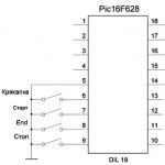
Many interesting electronic things are invented by people. So, for example, it occurs to many for different purposes to assemble a car stroboscope with their own hands, powered by an auto network. To assemble this device, it is advisable to use proven circuits, for example, one based on a 555 timer with a counter - ...

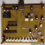
Not so long ago I assembled a module for an LED strobe. Two channels of 1 amp per channel with these TIP31C transistors, operate without a heatsink with the specified load. 7 modes of operation, switching via a button on the board or remote. List of components: - Microcontroller PIC12F675…

We will immediately warn you, additional light signals on a car are punishable by law. Therefore, the article is more exploratory in nature than practical. It is better to make a stroboscope at home than to fence it on a car. However, such a bauble would be quite appropriate somewhere outside the city at a night party. So let's move on...

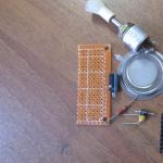
For a long time I dreamed of strobe lights in dimensions with my own hands and I think, why not try it. I tried it, and it turned out not bad strobe lights ... So the scheme. The scheme is not quite complicated. We make a board. This is my first time mastering LUT technology and I can say I liked it. 1. We sip ...

This craft, namely how to add strobe lights to DRL, has its pros and cons, but I think this will not stop craftsmen or someone who wants to repeat this scheme. Pros - you can wind up almost everything that fantasy is capable of, simple schemes for ...

In official documents, this device is called a special signal, and its scientific name is a stroboscope. Of course, there are many design differences between different stroboscopes, but they have a common principle of operation. In ordinary life, most often to see such a device in action happens in winter, when ...
Stroboscopes are used on cars to install the engine's ignition system. Such devices are sold in any auto shop. However, the device can be made by hand. The process of making a stroboscope will not take much time.
A stroboscope makes life much easier for its owner. With it, a driver with any level of experience will independently adjust the ignition angle. The device works due to the stroboscopic effect - a moving object is illuminated by a flash of light.
It is beneficial to have this device, since it will allow you to regulate the ignition yourself, without contacting service centers. And this will save money and time of the car owner. Some people do not trust homemade strobe lights, but they are just as good as store bought ones.

With "bare hands" it is difficult to adjust the ignition system. The stroboscope at times speeds up the time of setting the ignition of the car. The light in the strobe lamp signals that a spark has appeared, and this allows you to set the correct advance angle in the ignition system.
Factory appliances work efficiently and flawlessly, but they cost decently. Almost all such devices have an expensive lamp. If it fails - in fact, you have to buy a new device. Meanwhile, even at service stations, some craftsmen use homemade devices.
The most popular factory strobe lights:
- multitronics C2
- focusF1
- focusF10
- astrol5
The price of such devices reaches 6000 rubles. When making a stroboscope with your own hands, it will cost you - 600-700 rubles. Saving money by almost 10 times encourages you to make such a device yourself.
There are many schemes on the Internet on how to create a simple do-it-yourself strobe light. Most of them are quickly and easily assembled without requiring large financial investments. One of the most used schemes for creating a stroboscope on your own requires the following elements:
- copper wires;
- diode flashlight;
- capacitors c1;
- low frequency diode V2;
- specialized clamps;
- thyristor KU112A;
- resistors 0.125 W;
- meter power cord;
- relay with index RWH-SH-112D.
Such elements are sold at any radio market or electronics store. The body of the device is small. You can use the base of an old flashlight. 
- It is necessary to drill a hole for the power wire;
- Solder the clamps to the ends of the wires, observing the polarity;
- The sensor itself can be installed on the left or right;
- Copper wire must be soldered to the main core;
- All contacts must be isolated.
Such an invention is used to test the spark plug and the operation of the regulator.
The 155AG1 chip is considered the basis in such devices. To start it, pulses with negative polarity are needed. In such circuits, it is necessary to use resistances R3, R2, R1. They give limits on the fluctuations of the input signal. The duration of the pulses is provided by the capacitance C4 together with the resistor R6. By default, this value will be 2 ms. This circuit will be powered by a battery.

To make a device yourself using a timer, you need to make more efforts than for a simple strobe. The main advantage of such a device is constant light pulses that do not depend on the battery voltage. A stroboscope such as a tachometer is used. To do this, you need to switch the regulator.

For the correct operation of a homemade device, it must be checked. From the existing device, it is necessary to set the lead angle.
For this you need:
- warm up the engine and leave it idling;
- connect the device to the battery;
- wind the copper sensor around the core of the cylinder;
- orient the light source according to the special designation on the body;
- find a fixed point on the flywheel;
- to match the two points, it is necessary to rotate the ignition housing and keep it in a certain position.
The main point in the independent manufacture of a stroboscope is the correct assembly of the electrical circuit. Therefore, before starting manufacturing, it is recommended that you first make a detailed diagram. It will help to avoid errors during the assembly of the device.
Don't forget about safety. The stroboscope works under voltage. Do not allow the internal parts of the device to touch its body, especially metal.
It is good if the variable resistor is protected by a plastic handle. A well-insulated power cord must have a plug. All parts must be installed on a special board made of insulating material. The location of all the parts is not important, but it is necessary to mount them following a special scheme. Fastening all the details is required very carefully.
If difficulties arise in the manufacture of the device, it is best to contact a knowledgeable person. As an alternative to a "live" assistant - a detailed video tutorial describing the manufacturing process and operation of the stroboscope:
Stroboscopes are used on cars to adjust the ignition system of the power unit. This device can be purchased at any auto shop. But the device can be made independently. The process of making a stroboscope yourself does not take much time. More on this later in the article.
A stroboscope makes life much easier for its owner.
Thanks to him, even an inexperienced motorist can independently adjust the ignition angle. The work of the stroboscope is based on the stroboscopic effect - a moving object is illuminated by a light flash.
It is beneficial to have such a device, as it makes it possible to independently regulate the ignition without contacting a service center, which saves time and money for the car owner. There are such motorists who prefer factory strobe lights, not trusting home-made ones, but they are no worse than traditional purchased ones.

Why is it difficult to set the ignition without a strobe
It is very difficult to adjust the ignition system with bare hands. The stroboscope allows you to speed up the ignition adjustment time of the vehicle several times. The light in the lamp of this device signals the formation of a spark, which makes it possible to set the correct advance angle.
Factory strobe, pros and cons
Factory devices work flawlessly and efficiently, but they cost decently. But in fact, all such devices have an expensive lamp, the failure of which leads to the acquisition of a new device. It is worth noting that even at the service station, some masters use home-made devices.
Top 5 Most Popular Factory Strobe Lights

The most popular factory-made strobe lights:


The cost of such devices reaches six thousand rubles. With self-manufacturing of a stroboscope, it will cost you about 600-700 rubles. So, saving money is actually ten times stimulating to make such a device with your own hands.
Spare parts and parts for making a stroboscope with your own hands
- LED flashlight.
- Copper wires.
- Capacitors c1.
- Specialized clamps.
- Low frequency diode V2.
- Resistors 0.125 V.
- Thyristor KY112A.
- Relay with index RWH-SH-112D.
- Meter cord.

Such parts and spare parts can be purchased at any electronics store or radio market. The body of the device is small. You can even use the base of an old flashlight.
Strobe circuit
There are a lot of schemes on the Internet on how to create a simple strobe yourself. Most of them are easily and quickly assembled without requiring significant financial investments.

Do-it-yourself stroboscope assembly, step by step, the easiest option
Sequencing:
- Drill a hole for the power cable.
- Observing the polarity, solder the clamps to the ends of the wires.
- The sensor can be installed on the right or left.
- We solder the copper wire to the main core.
- Isolate all contacts.
This invention is used to test the operation of the regulator and the spark plug.
Timer based strobe, pros and cons
To independently make a device using a timer, you need to make more efforts than for a conventional stroboscope. The key advantage of such a device is constant light pulses, which do not depend on the voltage of the battery. A stroboscope such as a tachometer is used. To do this, you need to switch the regulator.

LED stroboscope, pros and cons
The basis of such devices is the 155AG1 chip, which requires pulses with negative polarity to run. In such circuits, it is necessary to use resistances R1, R2, R3. They limit fluctuations in the input signal. This circuit will be powered by a battery. The duration of the pulses is able to provide capacitance C4 with resistor R6. According to the classic settings, this value will be equal to 2 ms.

How to use homemade strobe lights
For the correct functioning of a home-made device, it must be checked. From the existing device, you need to set the lead angle:
- First, we warm up the power unit and leave it to function at idle.
- Connect the device to the battery.
- We wind the copper sensor around the core of the cylinder.
- Next, you should orient the light source according to a special indicator on the body.
- We are looking for a fixed point on the flywheel.
- To make the two points match, rotate the ignition housing and keep it in the desired position.
The key point in self-manufacturing of this device is the correct assembly of the electrical circuit. That is why, before starting manufacturing, it is imperative that you first make a detailed diagram that will help to avoid errors when assembling the device.
Do not forget about safety precautions. Any strobe operates under voltage. The internal elements of the device must not be allowed to touch its body, especially metal.
It is desirable that the variable resistor be protected by a plastic handle. A well-insulated power cord must have a plug. All parts must be mounted on a special board made of insulating material. Parts are mounted according to a special scheme, but their location is not important. It is necessary to carefully fasten all the elements.
Related Articles